Eureka AIR delivers breakthrough ideas for toughest innovation challenges, trusted by R&D personnel around the world.

Simple electric welding machine secondary line and weldment lap joint device

A lapping device and secondary line technology, applied in the direction of electrical component connections, electrical components, conductive connections, etc., can solve problems such as irregular welding operations, large oil stains on the surface of welded parts, and cumbersome tasks, so as to avoid unsafe behaviors, The effect of improving welding efficiency and reducing production costs

Pending Publication Date: 2020-10-16
BAOTOU IRON & STEEL GRP
View PDF0 Cites 0 Cited by
  • Summary
  • Abstract
  • Description
  • Claims
  • Application Information

AI Technical Summary

Problems solved by technology

[0002] At present, the iron and steel industry, as a traditional basic industry, is limited by the industry's own characteristics, and it is difficult to manage the site according to the 6S standard. However, with the needs of industrial development in recent years, high-quality development requires the entire industry to upgrade. What cannot be ignored is The iron and steel industry quickly gets rid of the old appearance of "dirty, messy, and poor", and gradually promotes clean production and standardized operations. For the current iron and steel industry, there are widespread habits such as irregular welding operations, habitual or unconscious illegal operations, etc., and specially invented simple electric welding The main reasons for the lapping device between the secondary line and the weldment of the machine are as follows: 1. Continuous production of the production line, welding operations often occur during minor repairs and shift shifts, the time is tight and the tasks are cumbersome, and continuous welding cannot be realized due to the secondary line falling off
2. The surface of the welding parts on site is heavily oily, and it is not easy to find a suitable position for the secondary line to overlap, and the phenomenon of poor circuit often occurs

Method used


Image

  • Simple electric welding machine secondary line and weldment lap joint device

Examples


Embodiment Construction

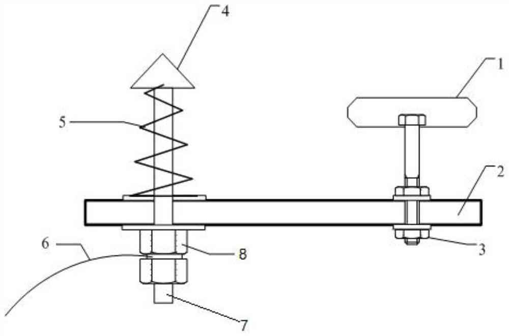
[0018] Such as figure 1 As shown, a simple welding machine secondary wire and weldment overlapping device includes a bakelite board 2, one end of the bakelite board 2 is fixedly connected with a strong magnet 1 through a first screw 3, and the other end of the bakelite board 2 A second screw rod 7 with a copper plug 4 is provided. The copper plug 4 and the strong magnet 1 are located on the same side of the bakelite 2. After the second screw 7 passes through the bakelite 2, the Two nuts 8 are threaded, and an adjustment spring 5 is set on the second screw rod 7 between the copper plug 4 and the bakelite 2. When the adjustment spring 5 is in a free state, the copper plug The distance between 4 and the bakelite board 2 is greater than the distance between the strong magnet 1 and the bakelite board 2, and the second screw 7 between the two nuts 5 is connected to the secondary wire 6 of the welding machine.

[0019] In the present embodiment, 1 piece of 10mm thick bakelite is dri...


PUM


Abstract

The invention discloses a simple electric welding machine secondary line and weldment lap joint device, which comprises a bakelite plate. One end of the bakelite plate is fixedly connected with a strong magnet through a first screw rod; the other end of the bakelite plate is provided with a second screw rod with a copper top head; the copper top head and the strong magnet are positioned on the same side of the bakelite plate; the second screw rod penetrates through the bakelite plate and then is fixed through two nuts in a threaded mode. An adjusting spring sleeves the second screw rod betweenthe copper top head and the bakelite plate, the distance between the copper top head and the bakelite plate is larger than the distance between the strong magnet and the bakelite plate when the adjusting spring is in a free state, and the second screw rod between the two nuts is connected with a secondary line of a welding machine. According to the simple electric welding machine secondary line and weldment lap joint device, the on-site welding efficiency can be improved, production is promoted, safe production is guaranteed, and meanwhile the corresponding production cost is reduced.

Description

technical field [0001] The invention relates to a simple type electric welding machine secondary wire and weldment overlapping device. Background technique [0002] At present, the iron and steel industry, as a traditional basic industry, is limited by the industry's own characteristics, and it is difficult to manage the site according to the 6S standard. However, with the needs of industrial development in recent years, high-quality development requires the entire industry to upgrade. What cannot be ignored is The iron and steel industry quickly gets rid of the old appearance of "dirty, messy, and poor", and gradually promotes clean production and standardized operations. For the current iron and steel industry, there are widespread habits such as irregular welding operations, habitual or unconscious illegal operations, etc., and specially invented simple electric welding The main reasons for the lapping device between the secondary line and the weldment of the machine are ...

Claims


Application Information

Patent Timeline
Patent Type & Authority Applications(China)
IPC IPC(8): H01R11/30H01R4/48
CPCH01R11/30H01R4/4863
Inventor 张川王亮
Owner BAOTOU IRON & STEEL GRP
Why Eureka
Eureka Blog
Learn More