Aircraft with double-fuselage tandem wing vertical take-off and landing layout

A technology of vertical take-off and landing and tandem wings, which is applied in the field of aviation aircraft and can solve the problems that aircraft cannot take off and land stably

Pending Publication Date: 2020-10-20
CHINA AERODYNAMICS RES & DEV CENT
View PDF9 Cites 2 Cited by
  • Summary
  • Abstract
  • Description
  • Claims
  • Application Information

AI Technical Summary

Problems solved by technology

[0003] The present invention intends to provide an aircraft with a vertical take-off and landing layout with twin fuselages an

Method used


Image

  • Aircraft with double-fuselage tandem wing vertical take-off and landing layout
  • Aircraft with double-fuselage tandem wing vertical take-off and landing layout
  • Aircraft with double-fuselage tandem wing vertical take-off and landing layout

Examples


Embodiment 1

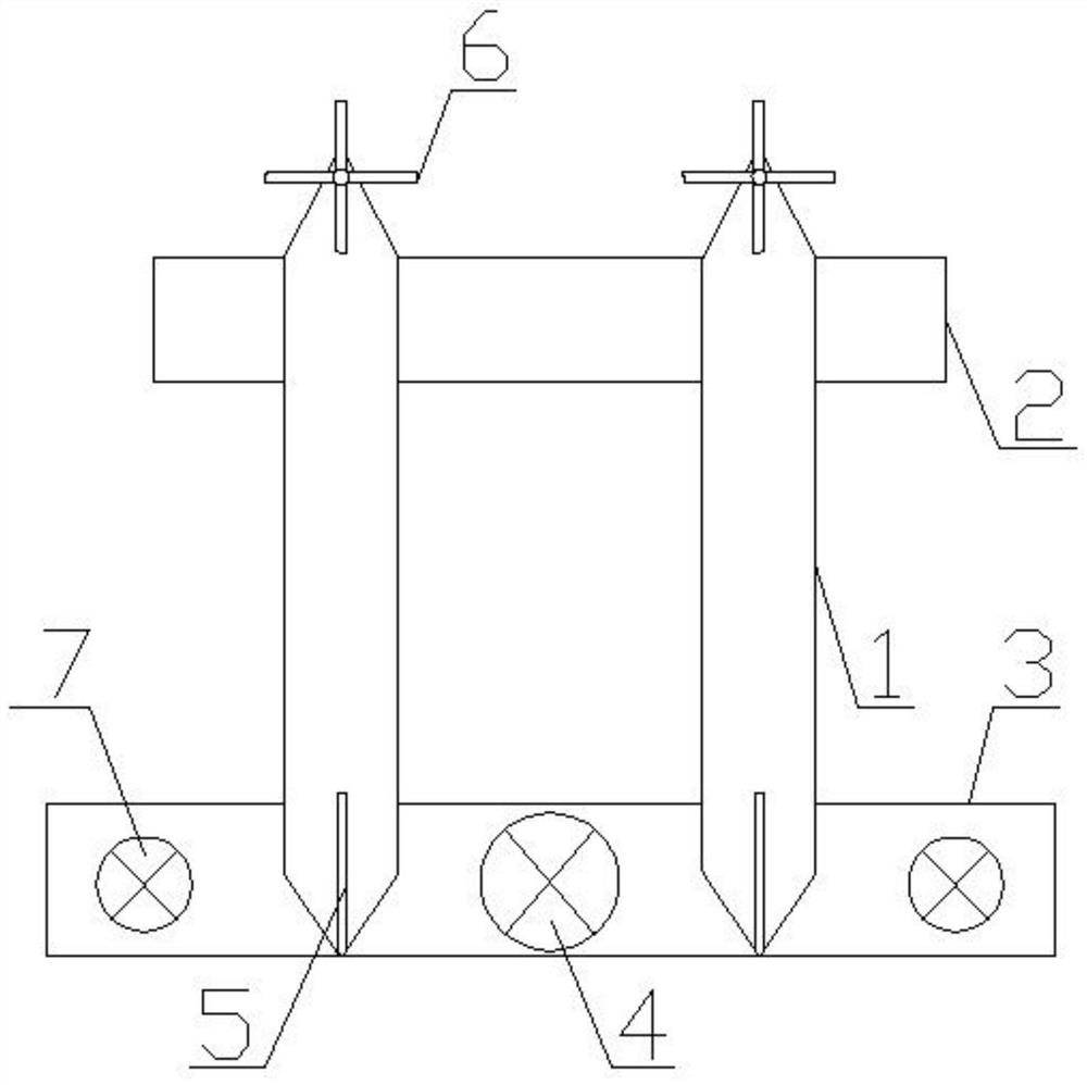
[0023] as attached figure 1 Shown: an aircraft with twin-fuselage tandem-wing vertical take-off and landing layout, including two fuselages 1 arranged at intervals. The use of twin-fuselage 1 can increase the load space of the whole aircraft and facilitate the loading of large-sized cargo or equipment. An engine is installed on the fuselage 1, and a front tandem wing 2 and a rear tandem wing 3 are welded at common intervals on the two fuselages 1, and the length of the front tandem wing 2 is shorter than that of the rear tandem wing 3, the rear tandem wing 3 is equipped with the first lift fan 4 between the two fuselages 1 and the slipstream rudder located below the first lift fan 4, and the first lift fan 4 is electrically connected to the engine , the first lift fan 4 adopts a closed lift fan, directly driven by the engine, with high hovering efficiency, heavy take-off weight, and large cargo load; heading control with the aid of slipstream rudders, high efficiency, large st...

Embodiment 2

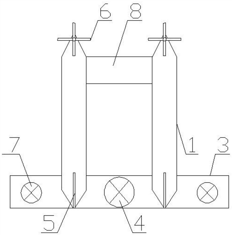
[0028] as attached figure 2 As shown, the difference between the present embodiment and embodiment 1 is only that the front tandem wing 2 is a canard 8. In this embodiment, the aircraft can generate trim and pitch control moments by means of the canard 8, which can better trim the aircraft.

Embodiment 3

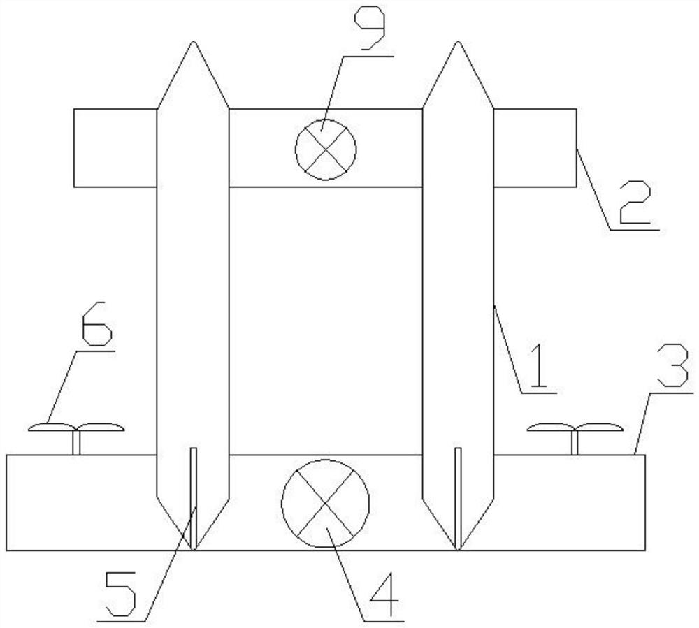
[0030] as attached image 3 As shown, an aircraft with a vertical take-off and landing layout with twin fuselages and tandem wings includes two fuselages 1 arranged at intervals. The use of twin fuselages 1 can increase the load space of the whole aircraft and facilitate the loading of large-sized cargo or equipment. An engine is installed on the fuselage 1, and a front tandem wing 2 and a rear tandem wing 3 are welded at common intervals on the two fuselages 1, and the length of the front tandem wing 2 is shorter than that of the rear tandem wing 3, the front tandem wing 2 is equipped with a second lift fan 9 between the two fuselages 1, the second lift fan 9 is electrically connected to the engine, and the front tandem wing 2 is opened for The duct of the second lift fan 9 is installed. The first lift fan 4 positioned between the two fuselages 1 and the slipstream rudder positioned below the first lift fan 4 are installed on the rear tandem wing 3, the first lift fan 4 is e...


PUM


Abstract

The patent of the invention discloses an aircraft with a double-fuselage tandem wing vertical take-off and landing layout, and particularly relates to the technical field of aviation aircrafts. The aircraft with a double-fuselage tandem wing vertical take-off and landing layout comprises two fuselages which are arranged at an interval, and an engine is arranged on each fuselage; a front tandem type wing and a rear tandem type wing which are distributed at an interval are arranged on the two fuselages; an electric tilting rotor wing arranged at one end of the front tandem type wing is also symmetrically arranged on each fuselage; a generator is connected between each electric tilting rotor wing and each engine, the generators are electrically connected with the engines, the rear tandem typewing is provided with a first lift fan located between the two fuselages and a sliding flow rudder located below the first lift fan, and each fuselage is provided with a vertical fin located at one end of the rear tandem type wing. By the adoption of the technical scheme, the problem that an existing aircraft cannot stably and vertically take off and land under severe weather conditions is solved, and the aircraft can fly under extreme weather conditions.

Description

technical field [0001] The invention relates to the technical field of aviation aircraft, in particular to an aircraft with a vertical take-off and landing layout with twin fuselages and tandem wings. Background technique [0002] In the field of aviation aircraft, vertical take-off and landing fixed-wing aircraft has great military and civilian value, and is the key direction of the development of aviation aircraft in various countries. Common vertical take-off and landing aircraft layout forms mainly include three types: compound type, tilting type and tail-sitting type. Most of the existing vertical take-off and landing fixed-wing aircraft have inherent defects such as poor wind resistance, insufficient take-off and landing stability, and limited load space. For example, the composite vertical take-off and landing layout adopts the rotor power design with high hovering efficiency, the downwash speed of the rotor is low, the vortex ring stalls easily, the load on the roto...

Claims


Application Information

Patent Timeline
IPC IPC(8): B64C27/26B64C29/00B64D27/02
CPCB64C27/26B64C29/00B64D27/02B64D2027/026
Inventor 杨小川付志肖涵山王海军毛仲君何炬恒何开锋姜久龙
Owner CHINA AERODYNAMICS RES & DEV CENT
Why Eureka
Try Eureka