Full-section welding construction method for curved steel box girder

A construction method and technology of steel box girder, applied in welding equipment, welding accessories, bridges, etc., can solve the problems of 87° curved steel box girder without mid-pier support and inability to perform full-span installation.

Inactive Publication Date: 2020-10-20
中铁九局集团第六工程有限公司 +1
View PDF6 Cites 0 Cited by
  • Summary
  • Abstract
  • Description
  • Claims
  • Application Information

AI Technical Summary

Problems solved by technology

[0002] In the prior art, the 87° curved steel box girder has no middle pier support, and cannot be installed across the entire span due to the impact of traffic

Method used


Image

  • Full-section welding construction method for curved steel box girder
  • Full-section welding construction method for curved steel box girder

Examples


Embodiment Construction

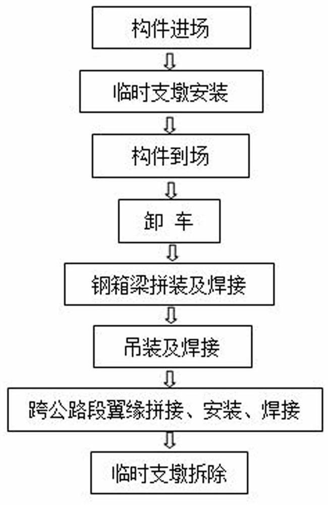
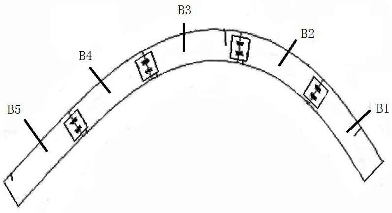
[0013] Such as figure 1 and figure 2 As shown, the full-section welding construction method of the curved steel box girder includes the following steps: 1) Components enter the site; 2) Temporary pier construction: a pier is set between two adjacent piers, and the pier adopts a steel structure lattice column , the height of the temporary pier is lower than the elevation of the bridge floor, the pier is welded on the pre-embedded steel plate, and the lower end of the pier is rigidly connected to the base plate; 3) Steel box assembly: assemble the on-site components to form sections B1, B2, Sections B3, B4, and B5, of which, sections B1 and B5 are straight sections, and sections B2, B3, and B4 are arc sections; 4) Steel box hoisting: hoist sections B1, B2, B3, and B3 in sequence Section flange, section B4 and section B5, section B1 and section B2 conduct air interface on the first temporary buttress, section B2 and section B3 conduct air interface on the second temporary suppo...


PUM


Abstract

The invention relates to a full-section welding construction method for a curved steel box girder, which is characterized in that temporary buttresses are built, the box girder is subjected to segmented installation and full-section welding, the erection and installation construction of the steel box girder is safely completed, the working efficiency is improved, and the influence on traffic operation is reduced.

Description

technical field [0001] The invention relates to a full-section welding construction method of a curved steel box girder, which belongs to the field of civil engineering. Background technique [0002] In the prior art, the 87° curved steel box girder has no middle pier support, and cannot be installed across the entire span due to traffic. Contents of the invention [0003] The technical problem to be solved by the present invention is to provide a construction method for full-section welding of curved steel box girders. By building temporary piers, the box girder is installed in sections and welded in full sections, so that the erection and installation of steel box girders can be safely completed and the work can be improved. efficiency and reduce the impact on traffic operations. [0004] In order to solve the above problems, the specific technical solution of the present invention is as follows: The full-section welding construction method of the curved steel box girde...

Claims


Application Information

Patent Timeline
IPC IPC(8): E01D21/00E01D2/04B23K9/16B23K9/235B23K9/32E01D101/30
CPCB23K9/16B23K9/235B23K9/32E01D2/04E01D21/00E01D2101/30
Inventor 杜以波许庆君金毓红刘京曲锐王颜辉赵志全杨勇李想郑智
Owner 中铁九局集团第六工程有限公司
Why Eureka
Try Eureka