Anti-blocking table type squatting pan

A squatting toilet and anti-clogging technology, applied in the field of sanitary ware, can solve problems such as clogging, small pipes, and long sewage pipes

Pending Publication Date: 2020-10-20
陈泳杰
View PDF0 Cites 0 Cited by
  • Summary
  • Abstract
  • Description
  • Claims
  • Application Information

AI Technical Summary

Problems solved by technology

[0003] The invention provides an anti-clogging desktop squatting pan, which aims to solve the problem that traditional squatting pans and toilets have long sewage pipes and small pipes, which are prone to blockage during use

Method used


Image

  • Anti-blocking table type squatting pan
  • Anti-blocking table type squatting pan
  • Anti-blocking table type squatting pan

Examples


Embodiment 1

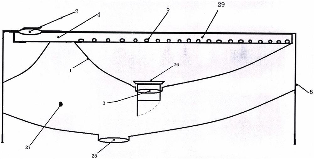
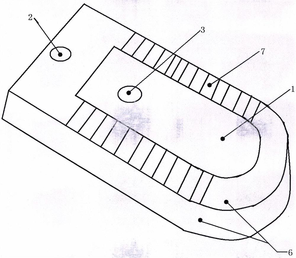
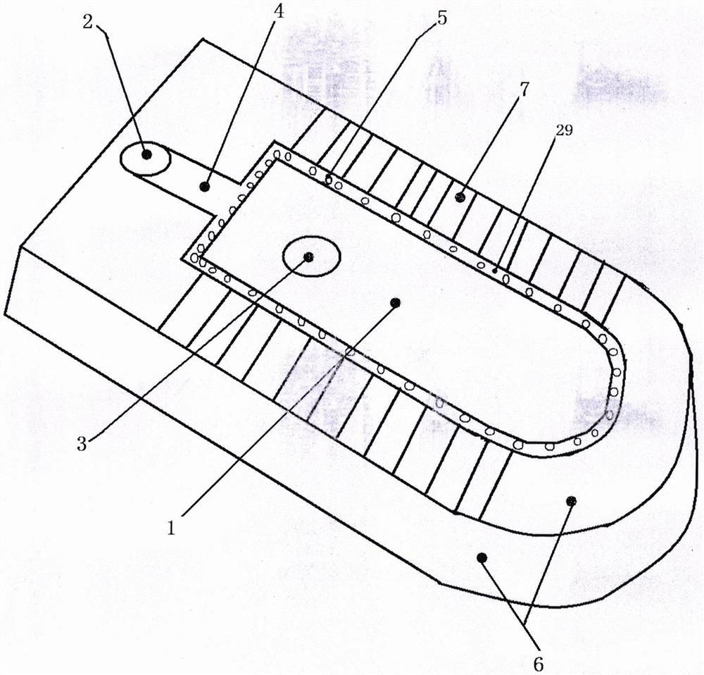
[0039] like figure 1 figure 2 image 3 Figure 10 Figure 11 Figure 12As shown, the present invention provides an anti-clogging desktop squatting pan, the squatting pan body 6 is a desktop squatting pan body, and the user is squatting to defecate; or it is a desktop toilet body, and the user is sitting defecation; The urinal 1, the sewage storage tank 27 is located inside the squatting pan body 6, the sewage storage tank 27 is located at the lower layer of the urinal 1, that is, the urinal 1 is located at the upper layer of the sewage storage tank 27, and the squatting pan body The height of 6 is greater than the total depth of the urinal 1 and the sewage storage tank 27, that is, the bottom of the sewage storage tank 27 does not protrude from the bottom of the squatting pan body 6: the urinal water inlet 2 is the top Water inlet, the urinal water inlet 2 is located on the top surface of the squatting pan body 6, the urinal water inlet 2 is connected to the flushing ch...

Embodiment 2

[0043] like Figure 5 As shown, the difference between this embodiment and Embodiment 1 is that the urinal water inlet 2 is a rear water inlet, the urinal water inlet 2 is located behind the squatting pan body 6, and the urinal water inlet 2 is connected to the Flush pipe 4.

Embodiment 3

[0045] like Image 6 Figure 7 As shown, the difference between this embodiment and Embodiment 1 is that it also includes a water tank 8 and a tank cover 10; the water tank 8 is located at the rear end of the surface of the squatting pan body 6; the inner bottom surface of the water tank 8 is provided with a urinal water inlet 2. Water tank water inlet 9, the water tank water inlet 9 is provided with one, the water tank water inlet 9 is used to install the water inlet device 18: the urinal water inlet 2 is used to install the drainage device 17: the water inlet The device 18 and the drainage device 17 are all prior art, and the present embodiment is not described in detail; the top surface of the water tank 8 is provided with a box cover 10; the box cover 10 is provided with a button mounting hole 11; the button mounting hole 11 It is used to install the flush button 19, and the flush button 19 is used to control the drainage device 17; the anti-clogging desktop squatting pan...


PUM


Abstract

The invention provides an anti-blocking table type squatting pan, and relates to the field of sanitary fittings. The squatting pan comprises a squatting pan body, a urinal, a urinal water inlet, a flushing channel, a urinal sewage draining exit, a magnetic sewage draining deodorizer, a sewage draining containing pool and a sewage draining exit. The squatting pan is characterized in that the urinaland the sewage draining containing pool are located in the squatting pan body, the top of the urinal is provided with the flushing channel, a water inlet port of the flushing channel is connected with the urinal water inlet, the bottom of the urinal is provided with the urinal sewage draining exit, the urinal sewage draining exit leads to the sewage draining containing pool, the bottom of the sewage draining containing pool is provided with the sewage draining exit, and the urinal sewage draining exit is provided with the magnetic sewage draining deodorizer. The anti-blocking table type squatting pan is not provided with a blow-off pipeline, and has the characteristics of deodorization function, clogging prevention, short blow-off distance, high blow-off speed and low water consumption.

Description

technical field [0001] The invention relates to the field of sanitary ware, in particular to a desktop squatting toilet and a toilet. Background technique [0002] like Figure 4 As shown, traditional squatting pans and toilets are provided with sewage pipes at the bottom of the urinal, and the sewage pipes are generally upwardly curved S-shaped or P-shaped traps, and the sewage pipes extend from the bottom of the urinal to the bottom of the urinal. At the sewage outlet on the ground or the wall, the sewage pipeline is long and small, and the problem of blockage is prone to occur during use. Contents of the invention [0003] The invention provides an anti-clogging desktop squatting pan, which aims to solve the problem that traditional squatting pans and toilets have long and small sewage discharge pipes and are prone to blockage during use. [0004] The present invention adopts the following technical solutions to achieve the above object. The anti-clogging desktop squat...

Claims


Application Information

Patent Timeline
IPC IPC(8): E03D11/04E03D11/02E03D11/13E03D11/17E03D11/10E03D1/26E03D1/00E03D5/00
CPCE03D1/003E03D1/26E03D5/006E03D11/02E03D11/04E03D11/10E03D11/13E03D11/17E03D2201/40
Inventor 陈泳杰
Owner 陈泳杰
Why Eureka
Try Eureka