Cement coating device for wall building

A cement and wall-laying technology, which is applied in construction, building structure, and building material processing, etc., can solve the problems of waste, cement easily falling to the ground, laborious and other problems.

Active Publication Date: 2020-10-20
凤阳凯晨建设工程有限公司
View PDF5 Cites 17 Cited by
  • Summary
  • Abstract
  • Description
  • Claims
  • Application Information

AI Technical Summary

Problems solved by technology

[0005] In order to overcome the shortcoming that people need to move tools continuously, it takes a long time, and it is more laborious, and in the process of moving tools back and forth, the cement is easy to fall to the ground and cause waste. The technical problem of the present invention is: to provide a more convenient This is a cement applicator for building walls that spreads cement evenly on bricks, saving effort and preventing waste from falling.

Method used


Image

  • Cement coating device for wall building
  • Cement coating device for wall building
  • Cement coating device for wall building

Examples


Embodiment 1

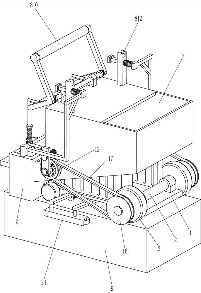
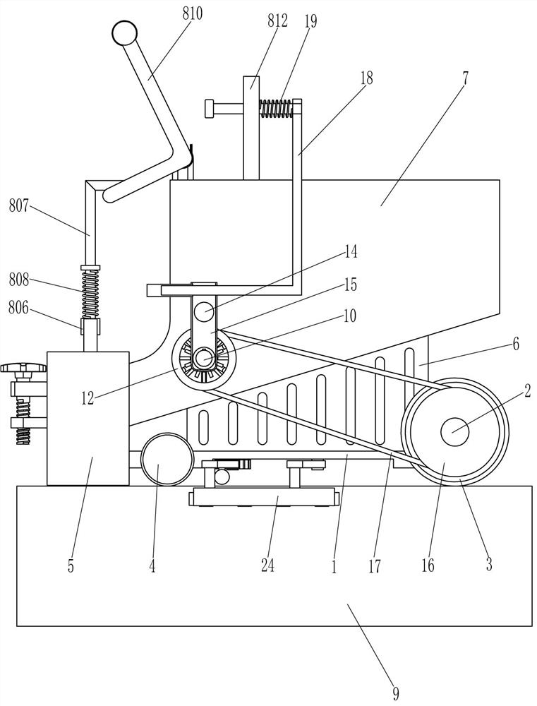
[0023] A cement smearing device for building walls, such as Figure 1-Figure 3 As shown, it includes a bottom plate 1, a first rotating shaft 2, a first roller 3, a second roller 4, a u-shaped frame 5, a support plate 6, a material storage box 7 and a smearing assembly 8, and the top right side of the bottom plate 1 is connected in a rotating manner. There is a first rotating shaft 2, the first rotating shaft 2 is fixedly connected with the first roller 3 in the circumferential direction, the left side of the front and rear sides of the bottom plate 1 is connected with the second roller 4 in a rotating manner, and the left side of the bottom plate 1 is fixed with a U-shaped frame 5, a support plate 6 is fixedly connected in the middle of the front and rear sides of the top of the bottom plate 1, and a storage box 7 is fixedly connected between the tops of the support plates 6 on the front and rear sides, and the discharge end of the storage box 7 is connected to the u-shaped fr...

Embodiment 2

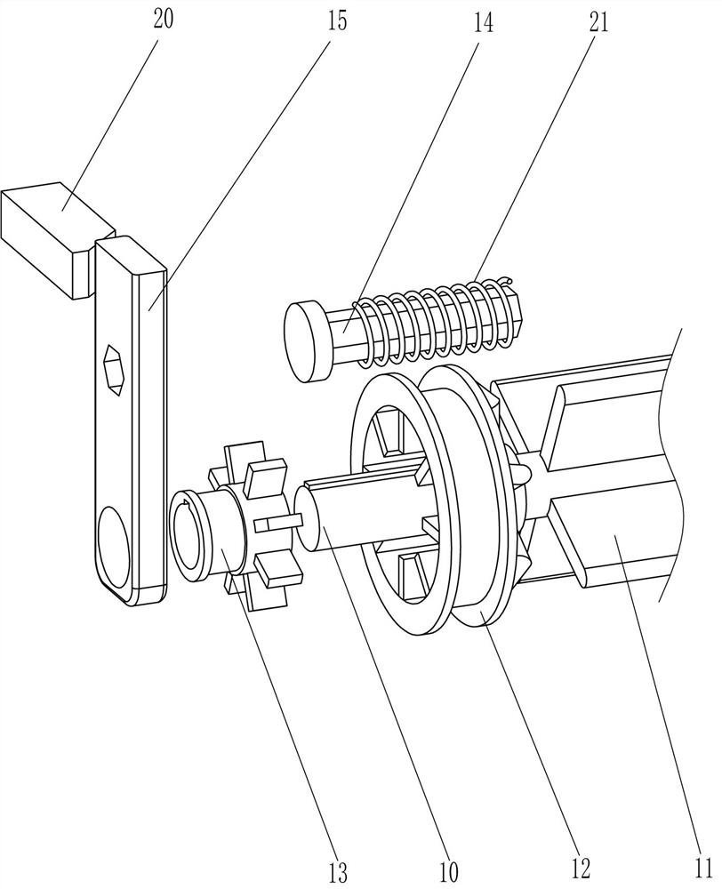
[0028] On the basis of Example 1, such as Figure 1-Figure 4 As shown, it also includes a second rotating shaft 10, a second scraper 11, a clutch drive wheel 12, a clutch sleeve 13, a hexagonal rod 14, a slider 15, a rotating drive wheel 16 and a belt 17, and the front and rear ends of the first rotating shaft 2 Both are fixedly connected with a rotating transmission wheel 16, and a second rotating shaft 10 is rotatably connected between the lower side of the left side of the front and rear sides of the storage box 7, and the two parts of the second rotating shaft 10 are rotatably connected with a clutch transmission wheel in the circumferential direction. 12. The clutch transmission wheel 12 is located outside the material storage box 7, and a belt 17 is wound between the clutch transmission wheel 12 on each side and the corresponding rotary transmission wheel 16, and the lower left side of the front and rear sides of the storage box 7 is fixed with hexagonal edges. Rod 14, o...

Embodiment 3

[0031] On the basis of embodiment 1 and embodiment 2, such as Figure 1-Figure 5 As shown, it also includes a sliding frame 18, a second spring 19, a wedge block 20 and a third spring 21, and the upper sliding type of the limit rod 812 is provided with a sliding frame 18 that cooperates with an L-shaped push frame 810. Inside the sliding frame 18 A second spring 19 is wound between the upper inner side of the right side surface and the upper right side surface of the limit rod 812, and the rear end of the lower part of the sliding frame 18 is fixedly connected with a wedge block 20 that cooperates with the slider 15, and the wedge block 20 is located at the bottom of the slider 15. On the left side, a third spring 21 is connected between the inner surface of the slider 15 and the outer surface of the material storage box 7 , and the third spring 21 is sleeved on the hexagonal rod 14 .

[0032] Also comprise rack bar 22, rotating bar 23, guide block 24, rotating block 25 and th...


PUM


Abstract

The invention relates to a coating device, in particular to a cement coating device for wall building. In order to solve the technical problems, the invention designs the cement coating device for wall building, which can uniformly coat cement onto bricks blocks more conveniently, saves labor and does not cause waste as cement is not liable to drop. The cement coating device for wall building comprises a bottom plate, wherein the edge of one side of the bottom plate is rotatably connected to a first rotary shaft; first rollers are fixedly connected on the first rotary shaft symmetrically; andthe first rollers are positioned at the two sides of the bottom plate. A proper amount of cement is poured into a storage box, the upper part of an L-shaped push frame is pulled to swing rightwards, abaffle plate moves upwards to not block cement, cement in the storage box is discharged into a u-shaped frame so as to be in contact with the brick blocks, and the L-shaped push frame is pulled to move rightwards, so that cement is uniformly coated onto the brick blocks, and the cement is coated onto the brick blocks without the needs of continuously moving a tool, and therefore, labor is saved,and cement is not liable to drop.

Description

technical field [0001] The invention relates to a smearing device, in particular to a cement smearing device for building walls. Background technique [0002] Building a wall is building a wall, and the strongest way to build a wall is to build it piece by piece. When building walls, most homeowners still choose conventional masonry construction methods as before. The walls of houses constructed in this way act as air temperature buffers, thus ensuring moderate indoor temperature and humidity. In addition, the thick brick wall also ensures a good sound insulation effect. When building a wall, it is necessary to lay the bricks. After laying a layer of bricks, it is necessary to apply cement to the bricks, and then lay the bricks on the cement. , making bricks to build a wall. [0003] At present, most of the cement is applied to the bricks with tools by hand. First, people use tools to dig up an appropriate amount of cement, and then move the tool to apply the cement to th...

Claims


Application Information

Patent Timeline
Patent Type & Authority Applications(China)
IPC IPC(8): E04G21/20
CPCE04G21/20
Inventor 不公告发明人
Owner 凤阳凯晨建设工程有限公司
Why Eureka
Try Eureka