Permanent magnet coupling direct drive device

A technology of permanent magnet coupling and permanent magnetic field, applied in permanent magnet clutches/brakes, electromechanical devices, electric brakes/clutches, etc., can solve the problem of large starting impact of permanent magnet synchronous motors and difficulty in directly starting large moment of inertia loads of asynchronous induction motors And other issues

Pending Publication Date: 2020-10-20
SHANGHAI ORIENTAL MARITIME ENG TECH CO LTD
View PDF0 Cites 0 Cited by
  • Summary
  • Abstract
  • Description
  • Claims
  • Application Information

AI Technical Summary

Problems solved by technology

[0006] The purpose of the present invention is to provide a permanent magnet coupling direct drive device, which integrates the advantages of permanent magnet synchronous motors and asynchronous induction motors, so

Method used


Image

  • Permanent magnet coupling direct drive device
  • Permanent magnet coupling direct drive device
  • Permanent magnet coupling direct drive device

Examples


Embodiment Construction

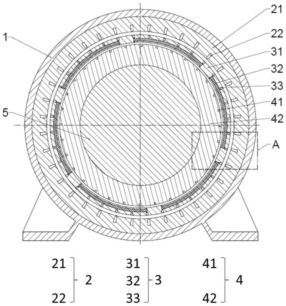
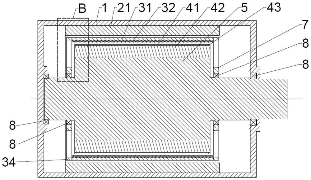
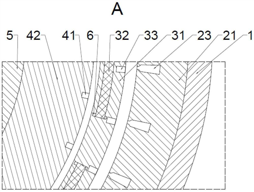
[0036] The following describes a permanent magnet coupling direct drive device proposed by the present invention in further detail with reference to the accompanying drawings and specific embodiments. The advantages and features of the present invention will become apparent from the following description and claims. It should be noted that, the accompanying drawings are all in a very simplified form and use imprecise ratios, and are only used to facilitate and clearly assist the purpose of explaining the embodiments of the present invention.

[0037] Also, expressions such as "first," "second," etc. are only used for the purpose of distinguishing between multiple configurations, rather than limiting the order among the configurations or other features.

[0038] In addition, the expression "comprising" an element is an "open-ended" expression, which merely refers to the presence of corresponding components and should not be interpreted as excluding additional components.

[00...


PUM


Abstract

The invention discloses a permanent magnet coupling direct drive device. The device comprises a casing, and a stator assembly, a permanent magnet rotor assembly, a conductor rotor assembly and an output shaft which are coaxially arranged in the casing in sequence from outside to inside. The output shaft is rotatably connected to the casing, and the conductor rotor assembly is fixedly connected tothe output shaft. The stator assembly is fixedly connected with the casing, and is used for communicating with external multi-phase alternating currents and generating a rotating magnetic field. The permanent magnet rotor assembly is rotationally connected with the casing or the output shaft and drives the permanent magnet rotor assembly to rotate through interaction of a permanent magnet field and a rotating magnetic field. The conductor rotor assembly cuts the rotating permanent magnetic field and generates torque, and the torque drives the conductor rotor assembly to rotate so as to drive the output shaft to rotate. The advantages of a permanent magnet synchronous motor and an asynchronous induction motor are integrated, and the problems that an existing permanent magnet synchronous motor is large in starting impact, locked-rotor is prone to demagnetization and the like and the problems that an asynchronous motor is low in efficiency, large rotational inertia loads are difficult todirectly start, locked-rotor is prone to burning and the like can be solved.

Description

technical field [0001] The invention belongs to the technical field of permanent magnet drive, and in particular relates to a permanent magnet coupling direct drive device. Background technique [0002] The permanent magnet synchronous motor adopts permanent magnet excitation, which has the advantages of high power factor, high efficiency, and a wide range of high-efficiency operation, and can be designed to directly drive the load with a high number of poles to shorten the transmission chain. For the asynchronous starting permanent magnet synchronous motor, during the starting process, the starting cage on the permanent magnet rotor cuts the rotating magnetic field generated after the stator winding is energized, thereby generating an induced current on the starting cage, thereby generating torque and driving the permanent magnet rotor to run. [0003] Asynchronous start-up permanent magnet synchronous motor has a short start-up time, which will cause the speed of the load ...

Claims


Application Information

Patent Timeline
IPC IPC(8): H02K49/04H02K49/10
CPCH02K49/043H02K49/106
Inventor 吴明马玉顺范欣马银飞何超江雯璟
Owner SHANGHAI ORIENTAL MARITIME ENG TECH CO LTD
Why Eureka
Try Eureka