Speed-controllable magnetic drive power generation system

A magnetic drive and power generation system technology, applied in electrical components, electromechanical devices, etc., can solve the problems of difficult rotation speed of magnetic drive devices, reducing enterprise efficiency, and energy consumption.

Inactive Publication Date: 2020-10-20
马冲 +1
View PDF0 Cites 0 Cited by
  • Summary
  • Abstract
  • Description
  • Claims
  • Application Information

AI Technical Summary

Problems solved by technology

Magnetic drives are becoming more and more popular. However, the common magnetic drive devices have complex structures and large losses. Especially for speed control, there is no good solution, which greatly reduces the efficiency of enterprises.
In addition, in the existing magnetic power generation system, small motors, magnetic coils, magnetic devices, mechanical devices, etc. are used to drive the rotating disk to rotate, and further drive the entire rotating shaft and rotor to rotate to achieve power generation. Usually, small generators, magnetic coils, and mechan

Method used


Image

  • Speed-controllable magnetic drive power generation system
  • Speed-controllable magnetic drive power generation system
  • Speed-controllable magnetic drive power generation system

Examples


Embodiment 1

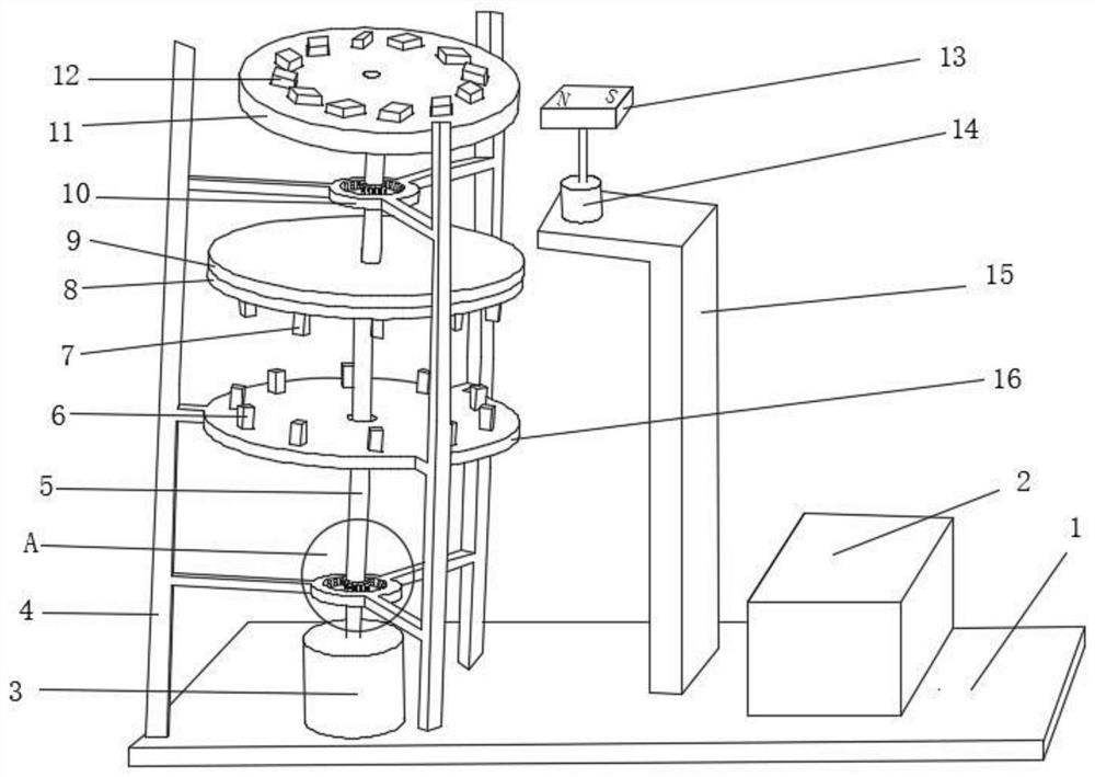
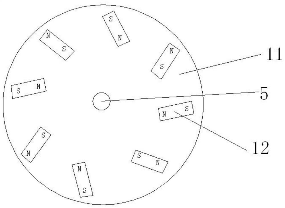
[0029] Such as Figure 1-4 As shown, the embodiment of the present invention provides a controllable speed magnetic drive power generation system, including a base 1, a support frame 4, a generator 3, a magnetic drive device, a central shaft 5, and a magnetic distance control component; the generator 3 is located on the base 1; the magnetic force distance control part includes an annular fixed mount 10 and a plurality of first magnets 18, and a plurality of the first magnets 18 are fixedly installed on the inner surface of the annular fixed mount 10; the circular The annular fixed frame 10 is fixedly connected with the support frame 4; the central shaft 5 passes through the ring center of the annular fixed frame 10, and the bottom of the central shaft 5 is fixedly connected with the rotor of the generator 3, and the central shaft 5. The top is fixedly connected with the magnetic driving device; the outer surface of the central shaft 5 is fixedly installed with a plurality of s...

Embodiment 2

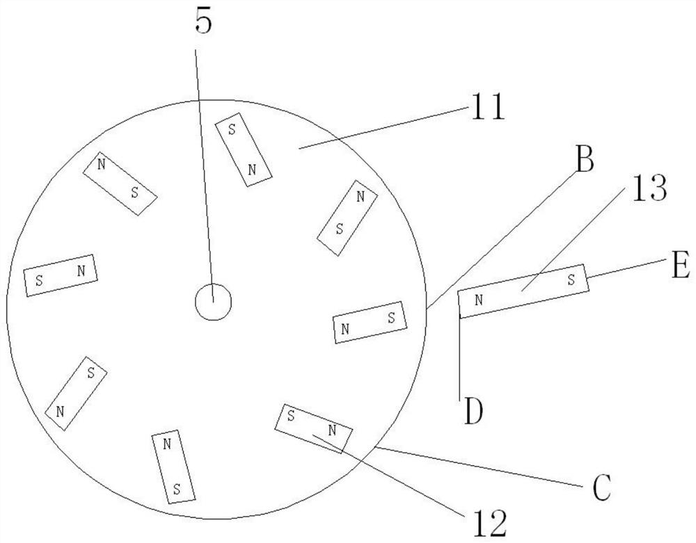
[0043] Such as Figure 5 As shown, the embodiment of the present invention provides a speed-controllable magnetic drive power generation system. The difference from the first embodiment is that the number of drive heads 13 in this embodiment is two groups, and the drive heads 13 surround the rotating disk 11 evenly. Distribution; each group of drive heads 13 corresponds to one drive motor 14 . The two driving heads 13 simultaneously drive the rotating disk 11, so that the driving force to the rotating disk 11 is more sufficient.

[0044] Further, the number of the driving heads 13 may be more than two groups.


PUM


Abstract

The invention relates to the technical field of magnetic power generation, and particularly discloses a speed-controllable magnetic drive power generation system which comprises a base, a supporting frame, a power generator, a magnetic drive device, a center shaft and a magnetic distance control component. The generator is arranged on the base; the magnetic distance control component comprises anannular fixing frame and a plurality of first magnets, and the first magnets are fixedly installed on the inner surface of a circular ring of the annular fixing frame; the center shaft penetrates through the center of a circular ring of the annular fixing frame, the bottom of the center shaft is fixedly connected with a rotor of the generator, and the top of the center shaft is fixedly connected with the magnetic drive device. A plurality of second magnets are fixedly installed at the positions, corresponding to the annular fixing frame, of the outer surface of the center shaft, and the polarities of the opposite sides of the first magnets and the second magnets are opposite. Through the magnetic distance control component, the suspension chassis and the like, the whole system is controlled in a suspended state by magnetic force, no mechanical contact exists in all directions, and the friction force is reduced.

Description

technical field [0001] The invention relates to the technical field of magnetic power generation, in particular to a speed-controllable magnetic drive power generation system. Background technique [0002] At present, the earth's resources are increasingly depleted, and magnetism can be used as a good energy source, and it is non-polluting, energy-saving and carbon-reducing. [0003] Magnetic drive generally uses the repulsive force of the same magnetic poles or the attractive force of opposite magnetic poles as the driving force. Magnetic drives are becoming more and more popular. However, the common magnetic drive devices have complex structures and large losses. Especially for speed control, there is no good solution, which greatly reduces the efficiency of enterprises. In addition, in the existing magnetic power generation system, small motors, magnetic coils, magnetic devices, mechanical devices, etc. are used to drive the rotating disk to rotate, and further drive the...

Claims


Application Information

Patent Timeline
IPC IPC(8): H02K53/00
CPCH02K53/00
Inventor 马冲吴少波
Owner 马冲
Why Eureka
Try Eureka