Electro-hydraulic unit

A hydraulic unit, electronic technology, applied to components with teeth, liquid variable displacement machinery, fluid pressure actuators, etc., can solve problems such as high development and manufacturing costs

Active Publication Date: 2020-10-20
SCHAEFFLER TECH AG & CO KG
View PDF6 Cites 0 Cited by
  • Summary
  • Abstract
  • Description
  • Claims
  • Application Information

AI Technical Summary

Problems solved by technology

This results in high development and manufacturing costs

Method used


Image

  • Electro-hydraulic unit
  • Electro-hydraulic unit
  • Electro-hydraulic unit

Examples


Embodiment Construction

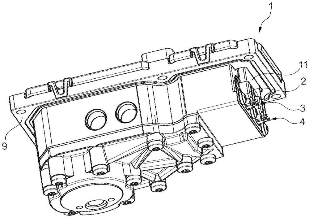
[0031] figure 1 A first variant of the electrohydraulic unit 1 is shown schematically in perspective from the outside. The electrohydraulic unit 1 has a housing 9 , which here is an injection-moulded aluminum housing. exist figure 1 , the housing 9 is open in the region of the crimping element 11 . The first hydraulic valve 3 and the second hydraulic valve 4 pass through the housing 9 in this region. The first hydraulic valve 3 and the second hydraulic valve 4 each have an electromagnet 2 . The first hydraulic valve 3 and the second hydraulic valve 4 are solenoid valves which are electrically conductively connected via crimp elements 11 to the PCB 8 , not seen here, of the electrohydraulic unit 1 .

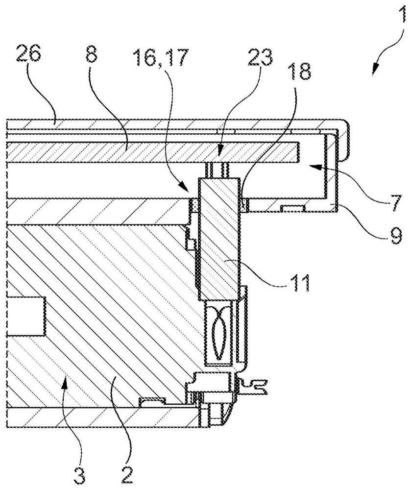
[0032] figure 2 A first variant of the electrohydraulic unit 1 in the region of the crimping element 11 is shown in longitudinal section. The PCB 8 of the control unit 7 of the electrohydraulic unit 1 is arranged in the housing 9 . The PCB 8 has a crimp area 23 with a contac...


PUM


Abstract

The invention relates to an electro-hydraulic unit (1) comprising at least one hydraulic valve (3, 4) activated by means of an electromagnet (2), at least one volume flow source (5), which comprises ahydraulic pump (31) driven with the aid of an electric motor (6), a control unit (7) having a PCB (8) for regulating or controlling a pressure and / or a volume flow and / or a direction of rotation of the pump (31), and a housing (9) accommodating the control unit (7), the volume flow source (8) and the at least one hydraulic valve (3, 4), characterized in that activation of the at least one hydraulic valve (3, 4) is carried out by the control unit (7) of the volume flow source (5), and a first electric contact (10) for the at least one hydraulic valve (3, 4) is provided directly on the PCB (8).The invention also relates to the use of PCB (8) with the same layout for a plurality of corresponding electro-hydraulic units which can be controlled via different control lines (19, 21).

Description

technical field [0001] The invention relates to the electric control of the electromagnetic valve of the electronic hydraulic unit. Such a unit can be used, for example, to operate or control a dual-clutch transmission having two or more clutches, or to operate or control a hybrid transmission in a motor vehicle. Background technique [0002] In addition to a hydraulic valve (solenoid valve) controlled by means of an electromagnet, such a unit also contains at least one volumetric flow source in the form of a hydraulic pump driven by an electric motor. The pump is equipped with a control unit in the form of a PCB (Printed Circuit Board) for regulating the pressure and / or volume flow and / or the direction of rotation, where the speed sensor, pressure sensor and / or temperature sensor are processed Signals and, if present, control commands from a higher-level control unit. For this purpose, the control unit is connected to at least one control line, which can be designed, for ...

Claims


Application Information

Patent Timeline
Patent Type & Authority Applications(China)
IPC IPC(8): F15B13/08F16H61/00F16H61/02
CPCF15B13/0853F15B13/0857F15B13/0892F16H61/0009F16H61/0206F04B7/0076F04B17/03F04B49/06F04B23/04F16H61/0006F16H2061/0253
Inventor 罗尚·维勒克托比亚斯·科宁格尔朱利安·博蒂奥夫马蒂亚斯·格伦茨霍泽尔克里斯托弗·施奈德马库斯·迪特里希西蒙·滕佩尔马丁·齐默尔曼彼得·比格尔特
Owner SCHAEFFLER TECH AG & CO KG
Why Eureka
Try Eureka