Al technical title is built by PatSnap Al team. It summarizes the technical point description of the patent document.
A technology of laser welding jig and clamping block, which is applied in the direction of laser welding equipment, welding equipment, welding equipment, etc., can solve the problems of workpiece clamping deformation, affecting the appearance of the workpiece, etc., and achieve the effect of preventing clamping damage
Inactive Publication Date: 2020-10-23
恒川激光(浙江)有限公司
View PDF1 Cites 9 Cited by
Summary
Abstract
Description
Claims
Application Information
AI Technical Summary
This helps you quickly interpret patents by identifying the three key elements:
Problems solved by technology
Method used
Benefits of technology
Problems solved by technology
[0003] The patent number is: CN201922063878.0, which discloses a clamping mechanism of a reversible laser welding machine. The clamping mechanism of a reversible laser welding machine can be adjusted according to the parts to be welded by setting the fixing parts and adjusting rods. The length and width improve the flexibility of the clamping mechanism, and at the same time, the limit rod improves the stability of the clamping to avoid loosening during welding; but there are shortcomings in this patent. During the clamping process, it is easy to deform the workpiece or leave clamp marks on the workpiece, which will easily affect the beauty of the workpiece
Method used
Image
Click on the blue label to locate the original text in one second.
Reading with bidirectional positioning of images and text.
Examples
Embodiment
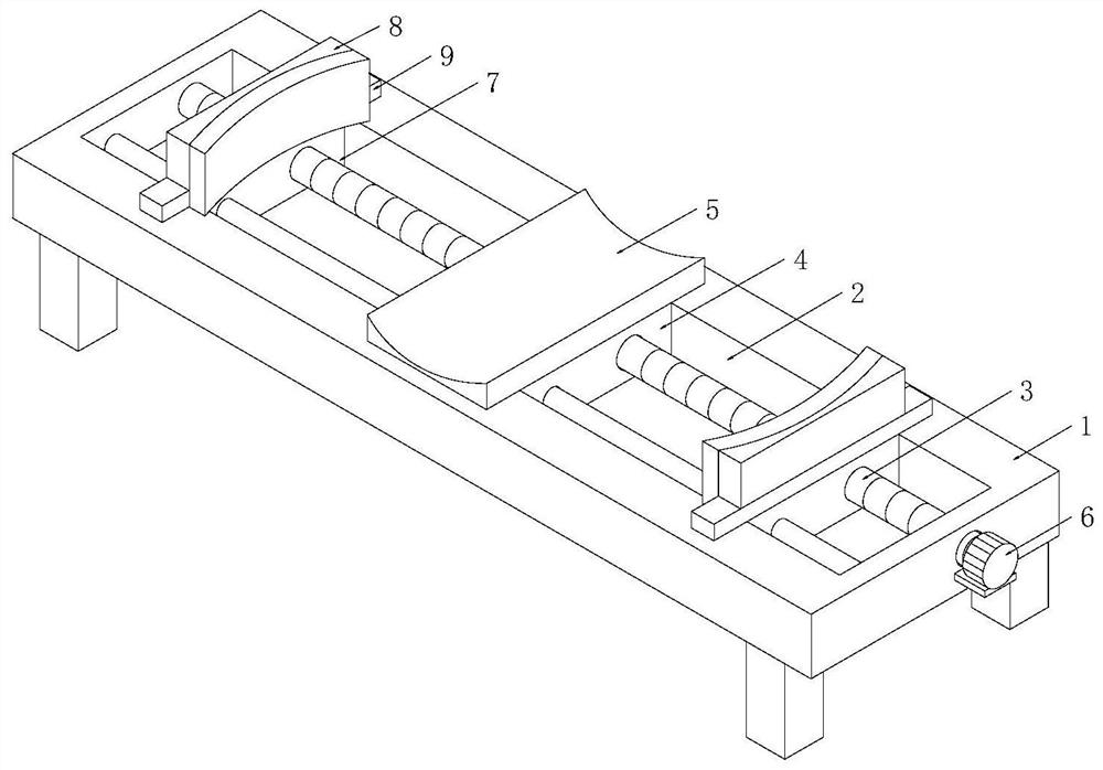
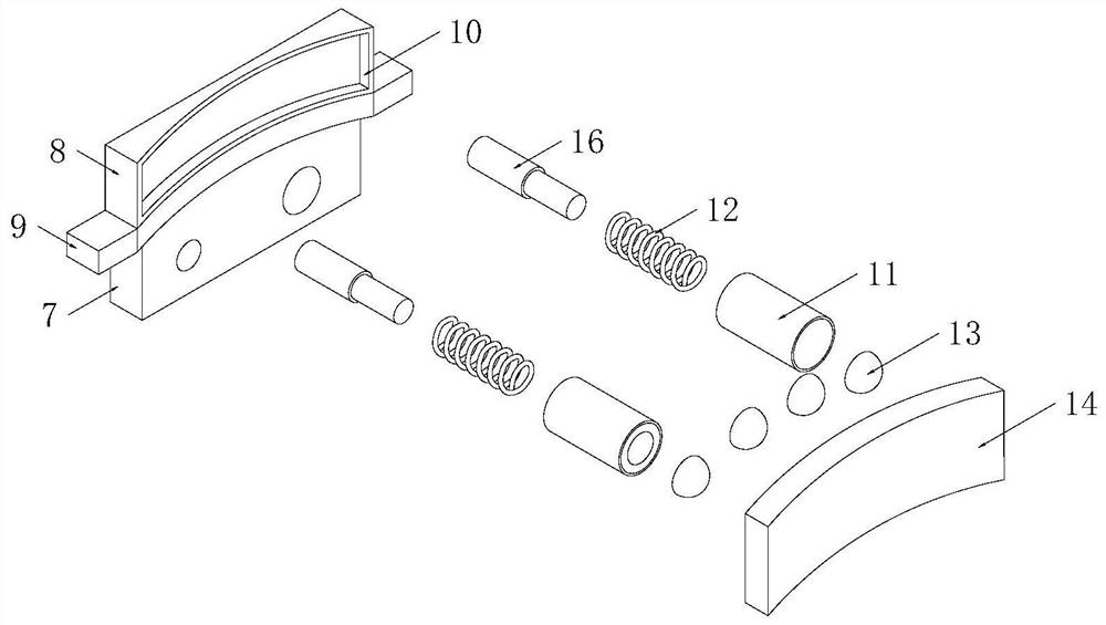
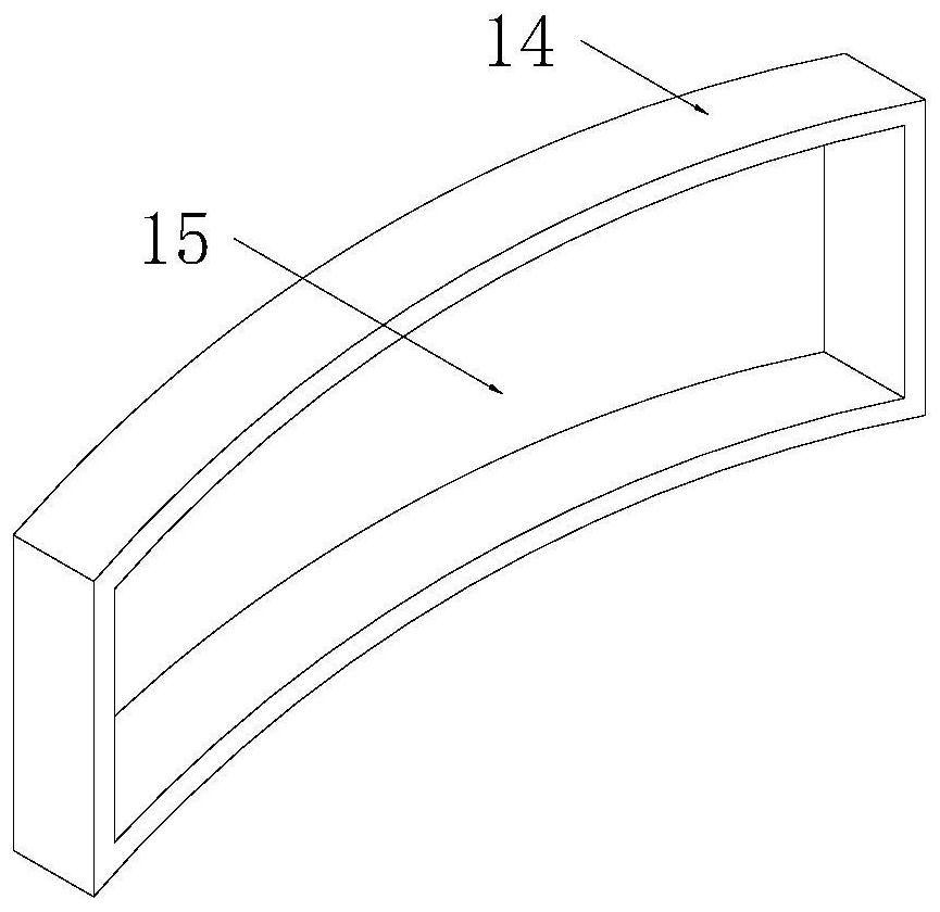
[0019] Example: such as figure 1 , figure 2 and image 3 As shown, the present invention provides a laser welding fixture, which includes: a workbench 1, a moving mechanism, two clamping mechanisms and two buffer mechanisms, the top of the workbench 1 is provided with a groove 2, and the moving mechanism is fixed Installed inside the groove 2, two clamping mechanisms are installed on the moving mechanism, the clamping mechanism includes a slider 7, a fixed plate 8, two limit blocks 9, a square groove 10 and a clamping block 14 , the bottom end of the slider 7 is set inside the groove 2, the bottom end of the fixed plate 8 is fixedly installed on the top of the slider 7, two limit blocks 9 are respectively fixedly installed on both sides of the fixed plate 8, and the square groove 10 Set on one side of the fixing plate 8 , one side of the clamping block 14 is arranged on one side of the fixing plate 8 .
[0020] Wherein, the moving mechanism includes a screw rod 3, a fixed ...
PUM
Abstract
The invention discloses a laser welding fixture. The laser welding fixture comprises a workbench, a moving mechanism, two clamping mechanisms and two buffering mechanisms, a groove is formed in the top end of the workbench, the moving mechanism is fixedly installed in the inner part of the groove, the two clamping mechanisms are installed on the moving mechanism, and each clamping mechanism comprises a sliding block, a fixing plate, two limiting blocks, a square groove and a clamping block. According to the laser welding fixture, the two clamping mechanisms are arranged on the workbench, the sliding block, the fixing plate, the square groove and the clamping block are arranged in each clamping mechanism, the sliding block is arranged on the moving mechanism in a sleeving mode, then the fixing plate is moved, the clamping block is moved, clamping can be carried out on a workpiece; meanwhile, a buffering mechanism is arranged on the square groove, and a spring, a telescopic rod, a rubbersleeve and an elastic ball are arranged in the buffering mechanism, so that when clamping is carried out on the workpiece, the buffering effect is achieved, and the workpiece is prevented from beingdamaged by clamping.
Description
technical field [0001] The invention relates to the field of welding, in particular to a laser welding jig. Background technique [0002] Laser welding is an efficient and precise welding method that uses a high-energy-density laser beam as a heat source; laser welding is one of the important aspects of the application of laser material processing technology; in the 1970s, it was mainly used for welding thin-walled materials and low-speed welding, welding The process is of heat conduction type, that is, the laser radiation heats the surface of the workpiece, and the surface heat diffuses to the interior through heat conduction. By controlling the parameters such as the width, energy, peak power and repetition frequency of the laser pulse, the workpiece is melted to form a specific molten pool. [0003] The patent number is: CN201922063878.0, which discloses a clamping mechanism of a reversible laser welding machine. The clamping mechanism of a reversible laser welding machin...
Claims
Application Information
Patent Timeline
Application Date:The date an application was filed.
Publication Date:The date a patent or application was officially published.
First Publication Date:The earliest publication date of a patent with the same application number.
Issue Date:Publication date of the patent grant document.
PCT Entry Date:The Entry date of PCT National Phase.
Estimated Expiry Date:The statutory expiry date of a patent right according to the Patent Law, and it is the longest term of protection that the patent right can achieve without the termination of the patent right due to other reasons(Term extension factor has been taken into account ).
Invalid Date:Actual expiry date is based on effective date or publication date of legal transaction data of invalid patent.