Pile foundation steel reinforcement cage anti-floating device and construction method of cast-in-place pile

A pile foundation steel cage and steel cage technology are applied in the direction of infrastructure engineering, sheet pile walls, buildings, etc., and can solve problems such as the floating of steel cages.

Pending Publication Date: 2020-10-23
CHINA MCC5 GROUP CORP
View PDF0 Cites 0 Cited by
  • Summary
  • Abstract
  • Description
  • Claims
  • Application Information

AI Technical Summary

Problems solved by technology

[0005] The technical problem to be solved by the present invention is to provide an anti-floating device for pile foundation reinforcement cages and a construction method for cast-in-situ piles, which solves the problem that the reinforcement cages float up during the construction of cast-in-place piles in the prior art

Method used


Image

  • Pile foundation steel reinforcement cage anti-floating device and construction method of cast-in-place pile
  • Pile foundation steel reinforcement cage anti-floating device and construction method of cast-in-place pile
  • Pile foundation steel reinforcement cage anti-floating device and construction method of cast-in-place pile

Examples


specific Embodiment 2

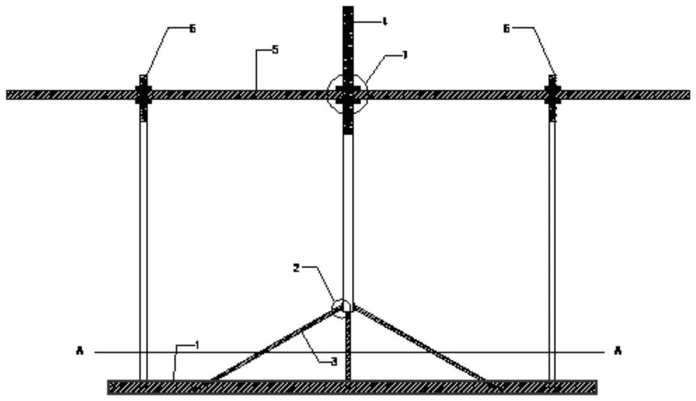
[0055] A construction method for cast-in-place piles, comprising the steps of:

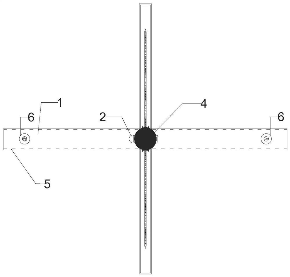
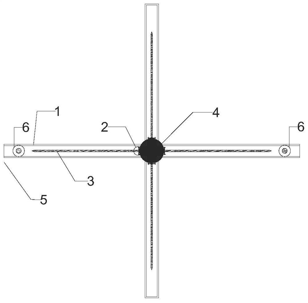
[0056] Step 1. Reserve two holes at both ends of any diameter of the steel casing for the passage of the bar-shaped channel steel in the anti-floating device of the pile foundation reinforcement cage;

[0057] Step 2, bury the steel casing, and after the hole forming and cleaning are completed, lower the reinforcement cage;

[0058] Step 3. After lowering the reinforcement cage, lower the anti-floating device of the pile foundation reinforcement cage except for the strip channel steel into the hole, and keep the bottom of the device below the bottom of the steel casing;

[0059] Step 4, pass the strip channel steel through the reserved hole of the steel casing;

[0060] Step 5, pass the screw rods at both ends of the cross-shaped track in the device and the threaded steel pipe placed in the center of the cross-shaped track through the reserved holes on the bar-shaped channel steel, and fix the sc...


PUM


Abstract

The invention discloses a pile foundation steel reinforcement cage anti-floating device. The pile foundation steel reinforcement cage anti-floating device includes a cross-shaped track and a bar-shaped channel steel; the cross-shaped track and the bar-shaped channel steel are connected to form a frame through connecting pieces; the frame is fixed at the lower end of the steel reinforcement cage; the two ends of the bar-shaped channel steel pass through the wall of the steel casing; and the cross-shaped track is located under the bar-shaped channel steel; wherein the center of the bar-shaped channel steel is provided with a reserved hole, a threaded steel pipe is penetrated into the reserved hole, and the lower end of the threaded steel pipe is provided with a steel drill in flexible connection that is connected in the circumferential direction; when the threaded steel pipe is pushed down, the free end of the steel drill moves in the cross-shaped track; and after the steel drill reachesa target position, the threaded steel pipe is fixed on the bar-shaped channel steel. The pile foundation steel reinforcement cage anti-floating device avoids the phenomenon that the steel reinforcement cage floats up when the concrete is poured, and improves the quality of the pile foundation. When the pile foundation steel reinforcement cage anti-floating device is used for the construction of acast-in-place pile, the device is not connected to the steel reinforcement cage, the base material is not damaged, and the device is easy to take out, which has high stability, can be reused many times, and is economical.

Description

technical field [0001] The invention belongs to the technical field of building construction, and in particular relates to an anti-floating device for a pile foundation reinforcement cage and a construction method for a cast-in-place pile. Background technique [0002] At present, in the construction of bridges and housing projects, it is often necessary to carry out cast-in-situ pile construction operations. Through mechanical punching, drilling operations or manual hole digging operations, after the completion of hole formation and hole cleaning, it is necessary to lower the reinforcement cage into the hole, and then Pouring concrete into piles. In the process of pouring concrete, when the concrete surface returns to the bottom of the reinforcement cage, due to the shallow buried depth of the conduit, the amount of concrete poured is relatively large, resulting in excessive return speed of the concrete, resulting in a large upward force, thus supporting The lifting condui...

Claims


Application Information

Patent Timeline
IPC IPC(8): E02D5/34E02D5/38E02D27/12
CPCE02D5/34E02D5/38E02D27/12E02D2250/0023E02D2300/002E02D2300/0029
Inventor 刘俊宇周世桥罗衡
Owner CHINA MCC5 GROUP CORP
Why Eureka
Try Eureka