
Outer loop fast cooling device for feed production

A technology of rapid cooling and external circulation, which is applied in household refrigeration devices, applications, household appliances, etc., can solve the problems of different feed cold and heat, the cooling effect cannot be guaranteed, and the quality of feed production is affected.

Pending Publication Date: 2020-10-23
安徽省天可饲料有限公司
View PDF1 Cites 1 Cited by
  • Summary
  • Abstract
  • Description
  • Claims
  • Application Information

AI Technical Summary

Problems solved by technology

[0002] Feed is the general term for the food of animals raised by all people. During the processing of feed, the heated and mixed raw materials need to be cooled and then stored. However, the cooling efficiency of traditional cooling devices is low, and the feed needs to be repeatedly turned to achieve the cooling effect. Cooling The range of the feed is not uniform enough, which will cause the feed to be cold and hot, and it is easy to mold during storage, which affects the quality of feed production. The existing patent application number is CN201921574957.1, which proposes a high-efficiency cooling device for feed production. The cooling is one-time cooling. This cooling method cannot guarantee that the material is finally cooled to the set temperature, and the cooling effect cannot be guaranteed. In view of the shortcomings of the existing device, an improved rapid cooling device is now provided.

Method used

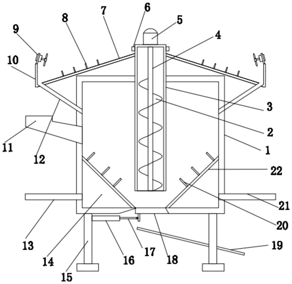

Image

  • Outer loop fast cooling device for feed production
  • Outer loop fast cooling device for feed production
  • Outer loop fast cooling device for feed production

Examples


Embodiment 1

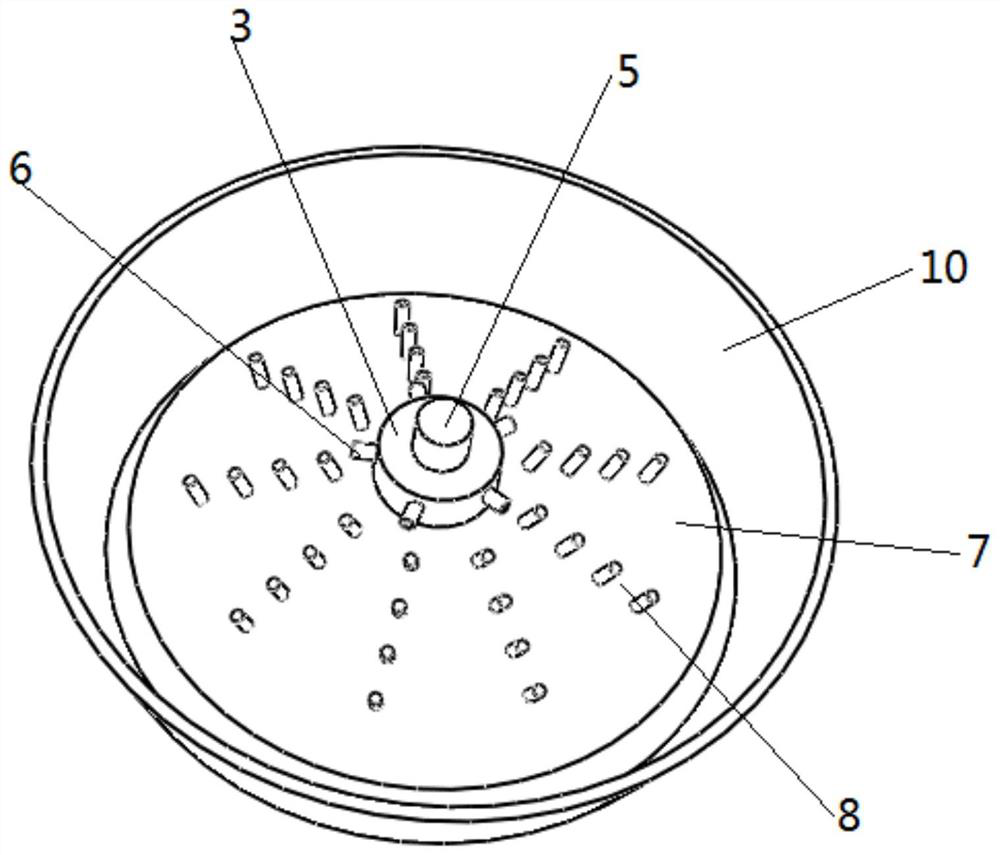
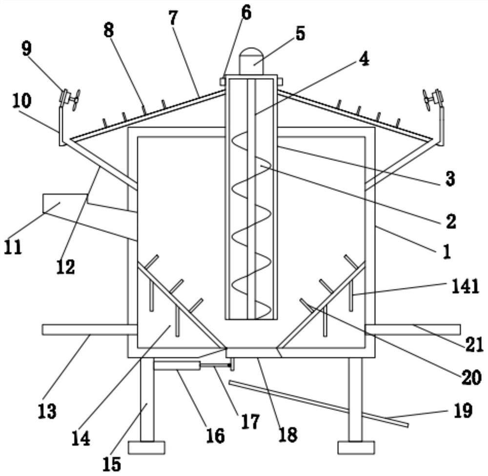
[0024] see Figure 1-3 In an embodiment of the present invention, a rapid cooling device for external circulation feed production includes a cooling box 1 and a plurality of legs 15 arranged in an array on its lower end surface, and a support block is provided at the lower end of each leg 15, The upper left side of the cooling box 1 is provided with a feeding pipe 11 for feeding, the bottom of the cooling box 1 is provided with a discharge assembly, and the cooling box 1 is provided with a first cooling member and a second cooling unit for cooling the material. pieces;

[0025] The first cooling member includes a lifting tube 3 that is installed on the top of the cooling box 1, and the lower end of the lifting tube 3 extends to the inner bottom of the cooling box 1. A rotating shaft 4 is arranged inside the lifting tube 3, and the outer side of the rotating shaft 4 It is equipped with a lifting blade 2 for lifting the material, and the upper end of the rotating shaft 4 is con...

Embodiment 2

[0033] The difference from Embodiment 1 is that: the conical guide hopper 22 is provided with several heat dissipation fins 141 on the side close to the cold water, and the heat dissipation fins are used to increase the heat dissipation area, thereby improving the heat dissipation effect.


PUM


Abstract

The invention discloses an outer loop fast cooling device for feed production. The outer loop fast cooling device comprises a cooler bin and a plurality of landing legs which are arranged on the lowerend face of the cooler bin and are distributed in array. A support block is arranged at the lower end of each landing legs. A feed pipe used for feed in materials is formed in the left upper side ofthe cooler bin. A discharge assembly is formed in the bottom of the cooler bin. A first cooling component and a second cooling component which are used for cooling the materials are arranged on the cooler bin. The first cooling component comprises a lifting tube which penetrates through the top of the cooling bin. The lower end of the lifting tube extends to the inner bottom of the cooling bin. The outer loop fast cooling device for feed production is designed by aiming at the disadvantages of the prior devices. The circulating cooling of the materials is achieved, the ultimate cooling qualityof the materials is ensured, and the cooling effect is further improved using a combination of an air-cooling method and a water-cooling method. Open-type cooling is adopted in the air-cooling, in addition, a subuliform structure is matched up to assist to disperse the materials, and the cooling effect is further improved.

Description

technical field [0001] The invention relates to the technical field of feed processing equipment, in particular to a rapid cooling device for external circulation feed production. Background technique [0002] Feed is the general term for the food of animals raised by all people. During the processing of feed, the heated and mixed raw materials need to be cooled and then stored. However, the cooling efficiency of traditional cooling devices is low, and the feed needs to be repeatedly turned to achieve the cooling effect. Cooling The range of the feed is not uniform enough, which will cause the feed to be cold and hot, and it is easy to mold during storage, which affects the quality of feed production. The existing patent application number is CN201921574957.1, which proposes a high-efficiency cooling device for feed production. The cooling is one-time cooling. This cooling method cannot guarantee that the material is finally cooled to the set temperature, and the cooling eff...

Claims


Application Information

Patent Timeline
Patent Type & Authority Applications(China)
IPC IPC(8): F25D31/00
CPCF25D31/00
Inventor 吴正东
Owner 安徽省天可饲料有限公司
Learn More