Depth measurement module and system

A depth measurement and module technology, which is applied in radio wave measurement systems, measurement devices, and electromagnetic wave re-radiation, etc., and can solve problems such as different application scenarios and application scenarios adaptability.

Pending Publication Date: 2020-10-23
DONGGUAN VISIONX-TECH CO LTD
View PDF0 Cites 5 Cited by
  • Summary
  • Abstract
  • Description
  • Claims
  • Application Information

AI Technical Summary

Problems solved by technology

Therefore, the application scenarios of iToF technology and dToF technology are different, and both face the adaptability problem of actual application scenarios

Method used


Image

  • Depth measurement module and system
  • Depth measurement module and system
  • Depth measurement module and system

Examples


Embodiment Construction

[0043] The technical solutions in the embodiments of the present application will be described below with reference to the drawings in the embodiments of the present application.

[0044] Before introducing the depth measurement module provided by the embodiment of the present application, in order to facilitate the understanding of this solution, the direct time-of-flight measurement method (abbreviated as dToF, hereinafter referred to as dToF) and the indirect time-of-flight measurement method (abbreviated as iToF) are first introduced here. , hereinafter referred to as iToF).

[0045] The measurement principle of dToF is: a high-precision time counter is used to synchronize with the optical signal transmitter. When the optical signal reflected from the object is detected, the time counter stops and the round-trip time of the optical signal is obtained. Since the speed of light is constant, thus The distance to be measured can be obtained.

[0046] The dToF product structur...


PUM


Abstract

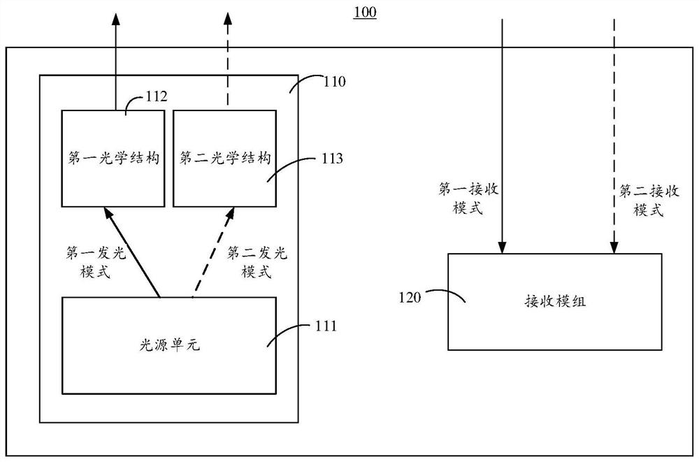
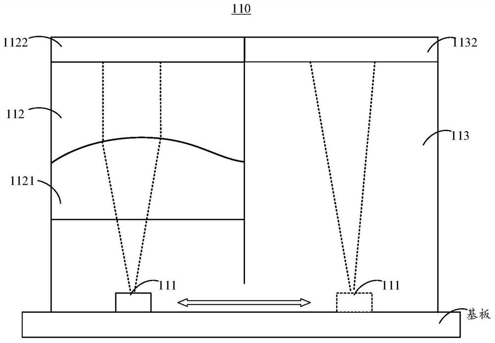
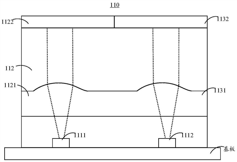
The invention provides a depth measurement module and system. The depth measurement module comprises: a projection module, which comprises a light source unit, a first optical structure and a second optical structure, wherein the light source unit comprises a first light-emitting mode and a second light-emitting mode, the light source unit projects a first picture into the space after light emitted by the first light-emitting mode passes through the first optical structure, and projects a second picture into the space after light emitted by the second light-emitting mode passes through the second optical structure; and a receiving module, which is used for receiving the first picture based on a first receiving mode so as to realize direct flight time measurement of a target object, and isalso used for receiving the second picture based on a second receiving mode so as to realize indirect flight time measurement of the target object. In this way, the depth measurement module can selecta proper flight time measurement mode under different distance and definition requirements, and the adaptability problem of the depth measurement module in different application scenes is effectivelysolved.

Description

technical field [0001] The present application relates to the technical field of depth measurement, in particular, to a depth measurement module and system. Background technique [0002] The time-of-flight method calculates the distance of an object by measuring the time of flight of light in space. There are mainly two methods. One is the indirect time of flight (indirect Time of Flight, referred to as iToF, indirect time of flight), and the other is the direct time of flight measurement method (direct Time of Flight, referred to as dToF, direct time of flight). [0003] Among them, iToF first emits a modulated optical signal, then measures the phase delay of the emitted optical signal and reflected optical signal, and then uses the delayed phase to calculate the flight time to obtain the measured distance. The high-precision time counter in the dToF system starts synchronously with the optical signal transmitter. When the optical signal reflected from the object is detec...

Claims


Application Information

Patent Timeline
Patent Type & Authority Applications(China)
IPC IPC(8): G01S17/10G01S17/894G01S7/484G01S7/4865G03B21/20
CPCG01S7/484G01S7/4865G01S17/10G03B21/2013G03B21/2033G03B21/206G03B21/208G01S17/894
Inventor 陈展耀郑祺戴书麟刘风雷
Owner DONGGUAN VISIONX-TECH CO LTD
Why Eureka
Try Eureka