
Focal plane image rotation mechanism

A technology of focal plane and image rotation, applied in the field of space optical remote sensing, which can solve the problem that the imaging quality depends on the image processing algorithm, etc.

Inactive Publication Date: 2020-10-23
CHANGCHUN INST OF OPTICS FINE MECHANICS & PHYSICS CHINESE ACAD OF SCI
View PDF6 Cites 0 Cited by
  • Summary
  • Abstract
  • Description
  • Claims
  • Application Information

AI Technical Summary

Problems solved by technology

At present, in the industry, the bias current is generally eliminated in the principle of instrument design, and the rotation axis of the instrument is designed according to the equator, so as to avoid the use of complex image rotation mechanism; or do not use the image rotation mechanism, but perform image rotation compensation through post-image processing , but the imaging quality of this method is highly dependent on the image processing algorithm, and there is no mature solution on the market

Method used


Image

  • Focal plane image rotation mechanism
  • Focal plane image rotation mechanism

Examples


Embodiment Construction

[0014] In order to make the purpose, technical solution and advantages of the present application clearer, the technical solution of the present application will be clearly and completely described below in conjunction with specific embodiments of the present application and corresponding drawings. Apparently, the described embodiments are only some of the embodiments of the present application, rather than all the embodiments.

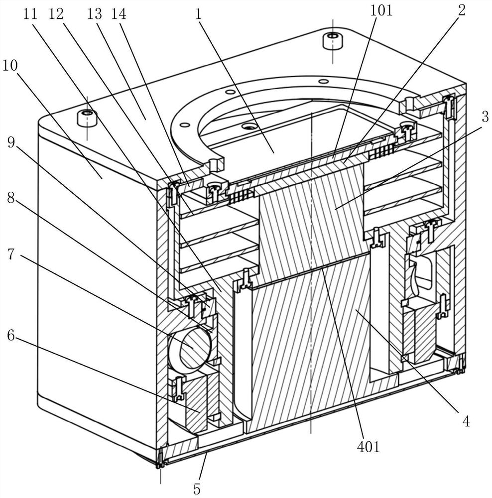
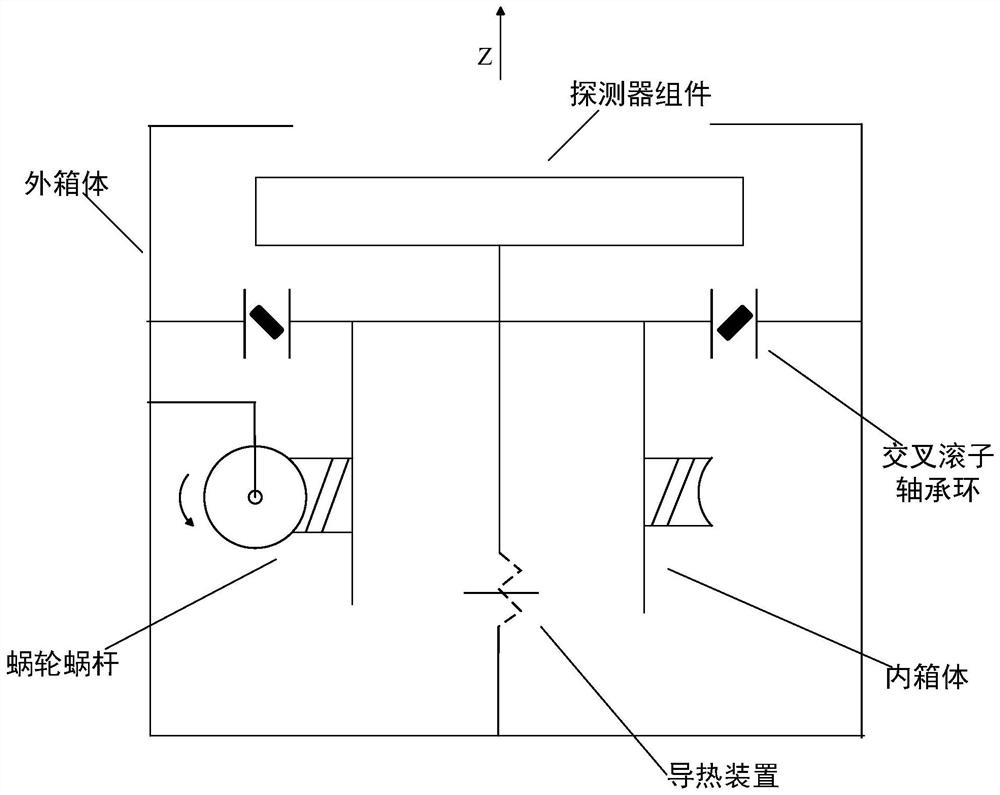
[0015] Please combine figure 1 and figure 2 , the focal plane image rotation mechanism of the present application includes an outer box 10 , an inner box 11 , a focal plane assembly 1 , a worm gear mechanism and an encoder 6 . The worm gear mechanism includes a worm wheel 8 and a worm 7. The inner box 11 is arranged in the outer box 10. The focal plane assembly 1 and the worm wheel 8 are both coaxially arranged and fixed to the inner box 11. The worm 7 passes through the bearing ( (not shown) is rotatably supported to the outer box body 10, and one...


PUM


Abstract

The invention provides a focal plane image rotation mechanism. The mechanism comprises an outer box body, an inner box body, a focal plane assembly, a worm and gear mechanism and an encoder, wherein the worm and gear mechanism comprises a worm gear and a worm, the inner box body is arranged in the outer box body, the focal plane assembly and the worm wheel are coaxially arranged and are both fixedto the inner box body, the worm is rotationally supported to the outer box body through a bearing, a shell of an encoder is fixed to the outer box body, an inner ring is matched with the inner box body, when image rotation compensation needs to be conducted, the worm drives the worm wheel to rotate, then the inner box body and the focal plane assembly are driven to rotate synchronously, and the encoder is used for reading the rotation tooth number of the worm wheel. The focal plane image rotation mechanism is simple in structure and can accurately adjust the rotation angle.

Description

technical field [0001] The invention belongs to the technical field of space optical remote sensing, and in particular relates to a focal plane image rotation mechanism. Background technique [0002] Remote sensing cameras are widely used in scientific research, military, agriculture, meteorology and other fields, and the focal plane assembly is one of the most critical parts of remote sensing cameras, the structural design of the focal plane assembly is particularly important. For some remote sensing cameras used in the aerospace field, in order to eliminate the influence of bias current on imaging, especially for remote sensing cameras with multiple detectors spliced ​​together, it is necessary to add an image rotation mechanism for image rotation compensation. At present, in the industry, the bias current is generally eliminated in the principle of instrument design, and the rotation axis of the instrument is designed according to the equator, so as to avoid the use of co...

Claims


Application Information

Patent Timeline
Patent Type & Authority Applications(China)
IPC IPC(8): G03B13/32H04N5/232
CPCG03B13/32H04N23/67
Inventor 赵越高志良张达刘衍峰刘栋斌李哲孙振亚王小朋李巍
Owner CHANGCHUN INST OF OPTICS FINE MECHANICS & PHYSICS CHINESE ACAD OF SCI
Learn More