
Laser output power control device and control method thereof

An output power and control device technology, applied in the laser output power control device and its control field, can solve the problems of the laser being unable to realize continuous adjustment and precise control of the laser output power, etc., and achieve the realization of rotation angle, noise reduction, and good control performance. Effect

Active Publication Date: 2022-05-13
INST OF MINERAL RESOURCES CHINESE ACAD OF GEOLOGICAL SCI +1
View PDF8 Cites 0 Cited by
  • Summary
  • Abstract
  • Description
  • Claims
  • Application Information

AI Technical Summary

Problems solved by technology

[0005] In view of the above analysis, the present invention aims to provide a laser output power control device and its control method to solve the problem that existing lasers cannot achieve continuous adjustment and precise control of laser output power

Method used


Image

  • Laser output power control device and control method thereof
  • Laser output power control device and control method thereof
  • Laser output power control device and control method thereof

Examples


Embodiment 1

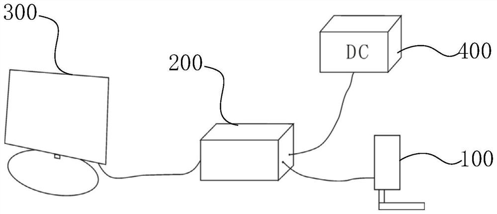
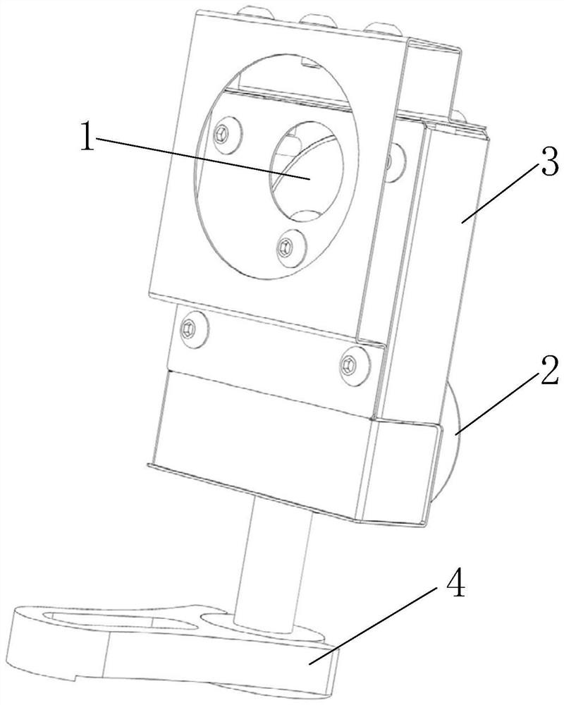
[0076] A specific embodiment of the present invention discloses a laser output power control device, which is used for power output regulation and precise control of a fixed power output laser.

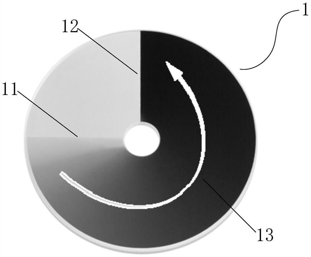
[0077] like Figure 1 to Figure 5 As shown, the laser output power control device includes:

[0078] The attenuator 100, the attenuator 100 includes a neutral attenuator 1 and a drive mechanism 2 for driving the neutral attenuator 1 to rotate; the surface of the neutral attenuator 1 has a coated attenuation area 13, and the attenuation area 13 has a first attenuation boundary 11 and the second attenuation boundary 12, the coating thickness from the first attenuation boundary 11 to the second attenuation boundary 12 increases linearly;

[0079] The controller 200, the controller 200 is electrically connected with the attenuator 100, and controls the rotation of the driving mechanism 2 based on a predetermined program to control the rotation angle of the attenuation area 13, so as to r...

Embodiment 2

[0095] Another specific embodiment of the present invention discloses a control method of a laser output power control device, that is, by controlling the laser output power control device of Embodiment 1, precise control of the laser output power is realized.

[0096] Figure 8 It is a flow chart of the control method of the laser output power control device of an embodiment, such as Figure 8 As shown, the control method of the laser output power control device in one embodiment includes step S100 to step S102:

[0097] S100, acquiring a calibration test result; wherein, the calibration test result includes a mapping relationship between a rotation angle and an output power;

[0098] S101, writing a predetermined program according to the calibration test result;

[0099] S102, sending the predetermined program to the controller 200, so as to instruct the controller 200 to control the rotation of the driving mechanism according to the predetermined program.

[0100] As in ...


PUM


Abstract

The invention relates to a laser output power control device and a control method thereof, belongs to the technical field of laser control, and solves the problem that an existing laser cannot realize continuous adjustment and accurate control of laser output power. The laser output power control device comprises an attenuator and a controller, and the attenuator comprises a neutral attenuation piece and a driving mechanism used for driving the neutral attenuation piece to rotate; the surface of the neutral attenuation piece is provided with a coating attenuation area, the attenuation area is provided with a first attenuation boundary and a second attenuation boundary, and the coating thickness from the first attenuation boundary to the second attenuation boundary is linearly increased; the controller is electrically connected with the attenuator and controls the driving mechanism to rotate based on a preset program so as to control the rotation angle of the attenuation area, and continuous adjustment and accurate control of the output power of the laser are achieved. The invention realizes the automatic power control of the fixed power output type laser, and has the advantages of convenience, rapidness, flexible control and accuracy.

Description

technical field [0001] The invention relates to the technical field of laser control, in particular to a laser output power control device and a control method thereof. Background technique [0002] The laser power output of existing commercial lasers is fixed, but in practical applications, it is often necessary to change the laser power to find the best excitation conditions. [0003] When using a laser Raman spectrometer to test and analyze the same sample, the spectral information obtained with different excitation powers is different. Taking Raman spectroscopy as an example, the Raman signal is a weak signal, and usually requires sufficient laser power to excite the sample to detect its Raman signal. In particular, molecular structures with weak Raman activity require strong laser power to be visualized. However, higher laser power may affect the molecular structure of the sample, such as causing disorder or phase transition of the chemical structure of the sample, wh...

Claims


Application Information

Patent Timeline
Patent Type & Authority Applications(China)
IPC IPC(8): G05D3/12H01S3/10
CPCG05D3/12H01S3/10
Inventor 杨丹杨军涛熊欣陈伟十王锟
Owner INST OF MINERAL RESOURCES CHINESE ACAD OF GEOLOGICAL SCI
Learn More