
Side frame groove processing method

A processing method and side frame technology, which are applied in the field of machining, can solve the problems that the chamfering process cannot be completely machined, the production efficiency is low, and the machining accuracy is low, and the invention can achieve high production efficiency, high machining accuracy, and improved production efficiency. Effect

Inactive Publication Date: 2015-09-09
ZHUZHOU ZHONGDA MACHINERY
View PDF4 Cites 0 Cited by
  • Summary
  • Abstract
  • Description
  • Claims
  • Application Information

AI Technical Summary

Problems solved by technology

In the prior art, the groove is generally processed by a CNC gantry milling machine, and the chamfering process cannot be completely machined. After milling and chamfering, the corners on both sides are manually polished, and the workpiece processing needs to be clamped twice. , Two tool changes completed
The existing K6 side frame groove processing method has low processing accuracy, high labor intensity and low production efficiency

Method used


Image

  • Side frame groove processing method
  • Side frame groove processing method
  • Side frame groove processing method

Examples


specific Embodiment approach

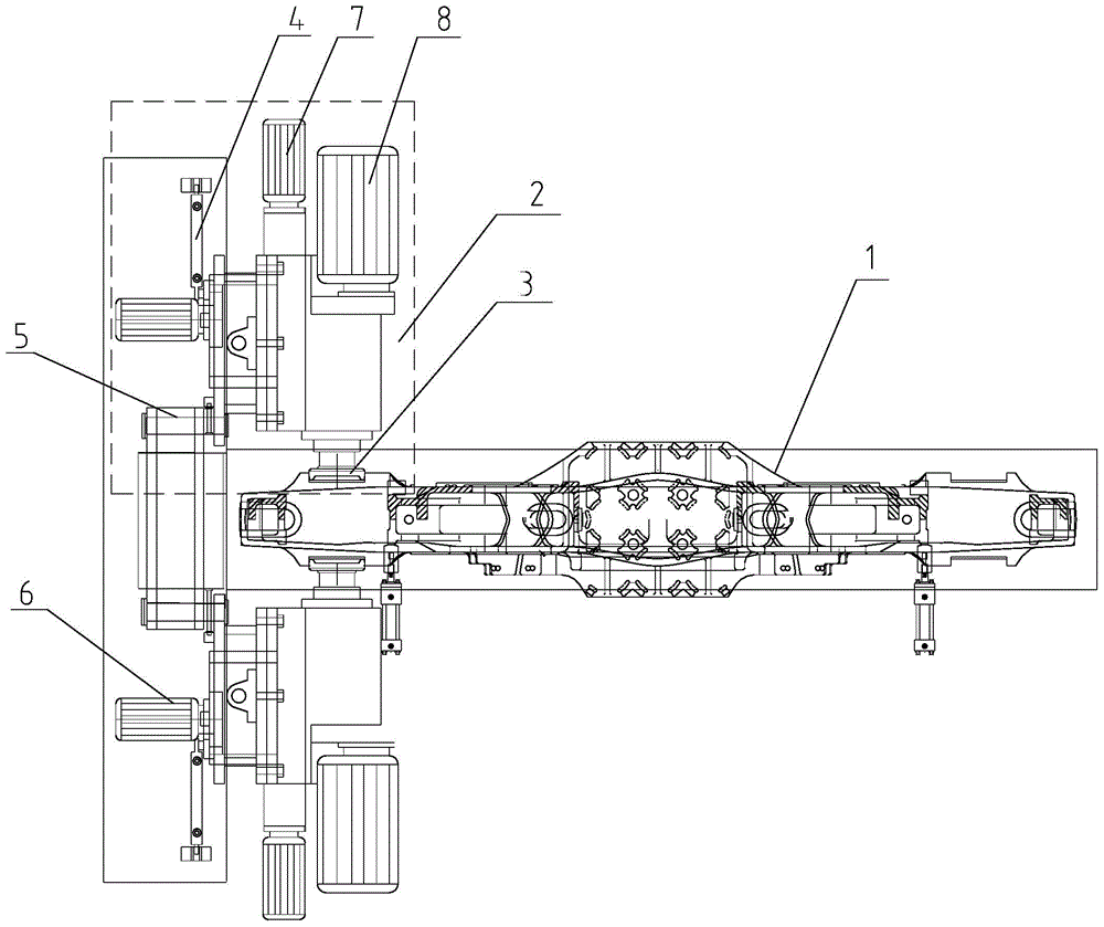
[0026] A method for processing side frame grooves, comprising the steps of:

[0027] a. Hoist the side frame workpiece to the side frame installation base, and fix it by clamping;

[0028] b. Taking the center line of the side frame as the line of symmetry, adjust the position of the power heads on both sides of the side frame so that the power heads are symmetrically distributed on both sides of the side frame; The ground is symmetrically distributed on both sides of the side frame, so that the power head can be precisely positioned during the groove processing process, and the processing accuracy of the groove chamfering is further improved;

[0029] c. Align the milling heads of the power heads on both sides of the side frame with the groove processing places on both sides of the side frame respectively, turn on the power head, and the milling heads of the two power heads feed at the same time to process the groove;

[0030] d. The two power heads are respectively connecte...


PUM

PropertyMeasurementUnit
Widthaaaaaaaaaa

Abstract

The invention discloses a side frame groove processing method. The method comprises the following steps: 1, hoisting a side frame workpiece to a side frame installation pedestal, and clamping for fixing; 2, adjusting the positions of power heads at two sides of the side frame with the center line of the side frame as a symmetric line in order to make the power heads symmetrically distributed at two sides of the side frame; 3, respectively aligning milling heads of the power heads at two sides of the side frame at groove processing positions at two sides of the side frame, starting the power heads, and allowing the milling heads of the two power heads to simultaneously advance in order to carry out groove processing; 4, respectively connecting the two power heads with rotating oil cylinders, starting the rotating oil cylinders after the groove processing, rotating the power heads 0-45DEG, and carrying out chamfering treatment on grooves processed in step 2 by the milling heads; 5, stopping the milling heads after the chamfering treatment, resetting the power heads, and disengaging the milling heads from side frame grooves; and 6, hoisting the processed side frame to a finished product zone. The side frame groove processing method has the advantages of high processing precision and high production efficiency.

Description

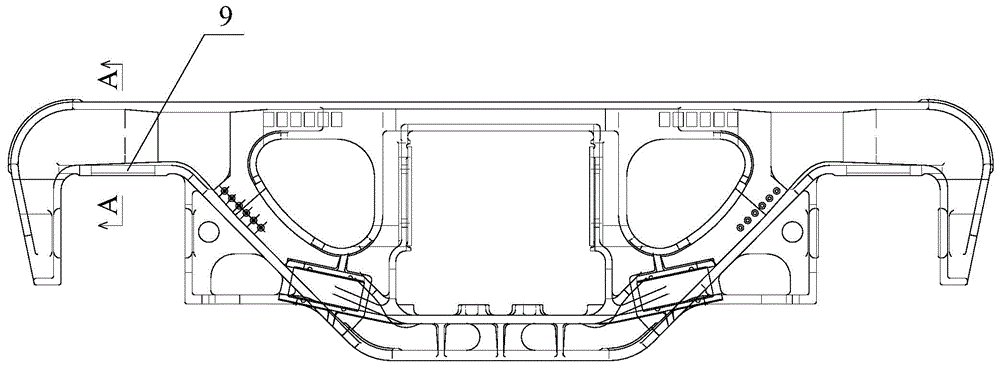
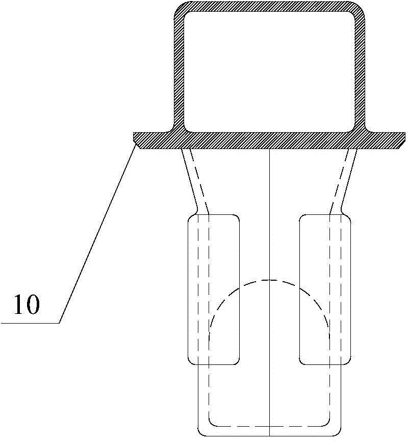
technical field [0001] The invention relates to the technical field of mechanical processing, in particular to a method for processing side frame grooves, and is particularly suitable for processing K6 side frame grooves. Background technique [0002] With the development of railways towards heavy load and high speed, heavy load and high-speed trucks have gradually become the mainstream models, and K6 side frame is one of the important accessories of heavy load and high-speed trucks. An important processing part of K6 type side frame is the groove and Chamfer. In the prior art, the groove is generally processed by a CNC gantry milling machine, and the chamfering process cannot be completely machined. After milling and chamfering, the corners on both sides are manually polished, and the workpiece processing needs to be clamped twice. , Two tool changes are completed. The existing K6 side frame groove processing method has low processing precision, high labor intensity and l...

Claims


Application Information

Patent Timeline
IPC IPC(8): B23C3/30
CPCB23C3/30
Inventor 刘忠钟颖
Owner ZHUZHOU ZHONGDA MACHINERY
Learn More