Battery pack

A battery and packaging technology, applied in the direction of batteries, battery pack components, circuits, etc., can solve the problems of useless space, energy density reduction, battery packaging size, weight increase, etc.

Active Publication Date: 2020-10-23
HONDA MOTOR CO LTD
View PDF13 Cites 4 Cited by
  • Summary
  • Abstract
  • Description
  • Claims
  • Application Information

AI Technical Summary

Problems solved by technology

[0007] However, conventional battery packs for vehicles have a structure in which a plurality of battery modules are accommodated inside the battery case and compressed in the stacking direction of the battery cells. The pressing phase in the state of the package is repeated, and as a result, there is a problem that the size and weight of the battery package increase
Furthermore, when a plurality of battery modules are accommodated inside the battery case, useless space may be generated, which may lower the energy density per unit volume of the battery package.

Method used


Image

  • Battery pack
  • Battery pack
  • Battery pack

Examples


no. 1 approach

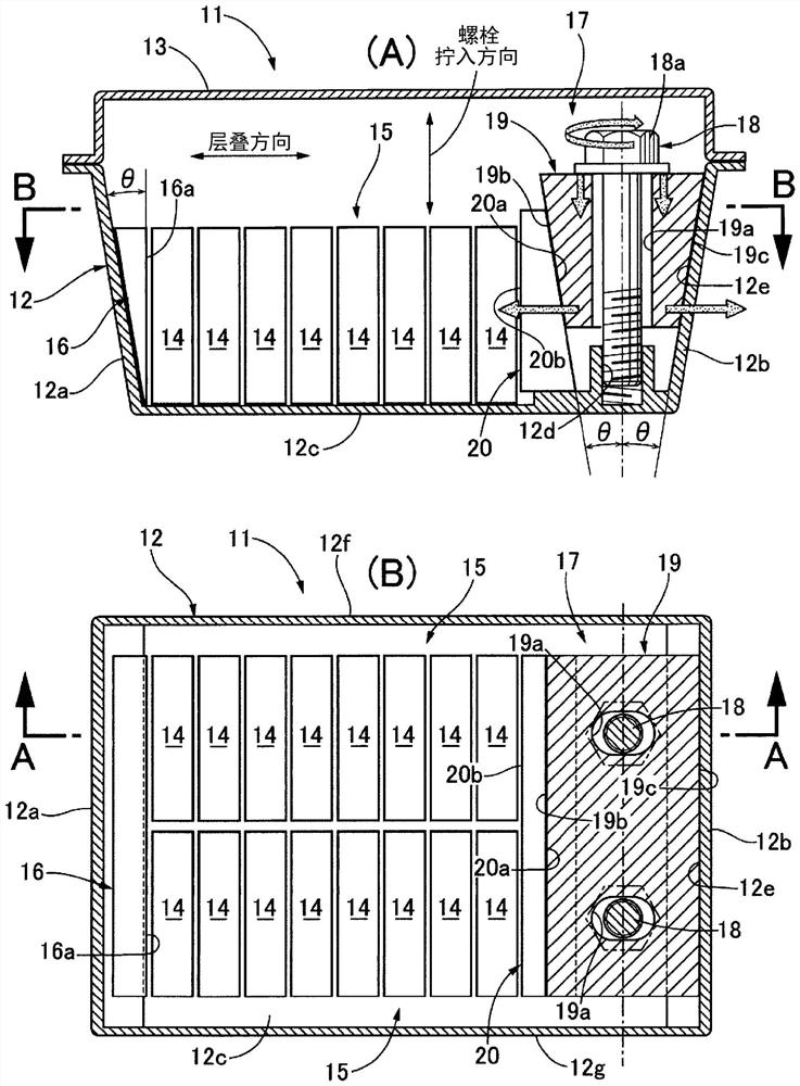
[0053] Below, based on figure 1 A first embodiment of the present invention will be described.

[0054] The battery pack 11 is formed by joining a container-shaped battery case 12 with an open upper surface and a battery cover 13 closing the opening of the upper surface of the battery case 12 at respective flanges. Inside, the several square unit body 14... which has a rectangular parallelepiped shape is accommodated in the state laminated|stacked along the lamination direction. A plurality of stacked square cells 14 ... constitute a cell stack 15 , and in the present embodiment, two cell stacks 15 , 15 are accommodated in the battery case 12 in parallel. Each cell stack 15 is different from conventional battery modules in that a plurality of rectangular cells 14... are only stacked in a free state, and are not compressed in the stacking direction.

[0055] When the battery case 12 made of aluminum is manufactured by die casting, the first side wall 12a and the second side w...

no. 3 approach

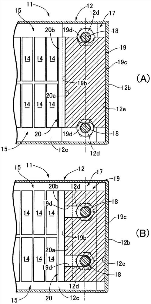
[0066] Next, based on figure 2 The second and third embodiments of the present invention will be described.

[0067] The wedge member 19 of the first embodiment has bolt holes 19a, 19a through which the bolts 18, 18 pass. figure 2 The wedge member 19 of the second embodiment shown in (A) has long groove-shaped bolt grooves 19d, 19d opened on both sides in the longitudinal direction, and bolts 18, 18 are fitted into these bolt grooves 19d, 19d from the side. in addition, figure 2 The wedge member 19 of the third embodiment shown in (B) has long groove-shaped bolt grooves 19d, 19d opened on its first abutting surface 19b, and bolts 18, 18 are fitted into these bolt grooves 19d, 19d from the stacking direction. combine.

[0068] According to these embodiments, since the bolts 18, 18 do not pass through the bolt holes 19a, 19a, it is only necessary to fit the bolts 18, 18 into the bolt grooves 19d, 19d from the side or the stacking direction, so the The assembly work of the...

no. 4 approach

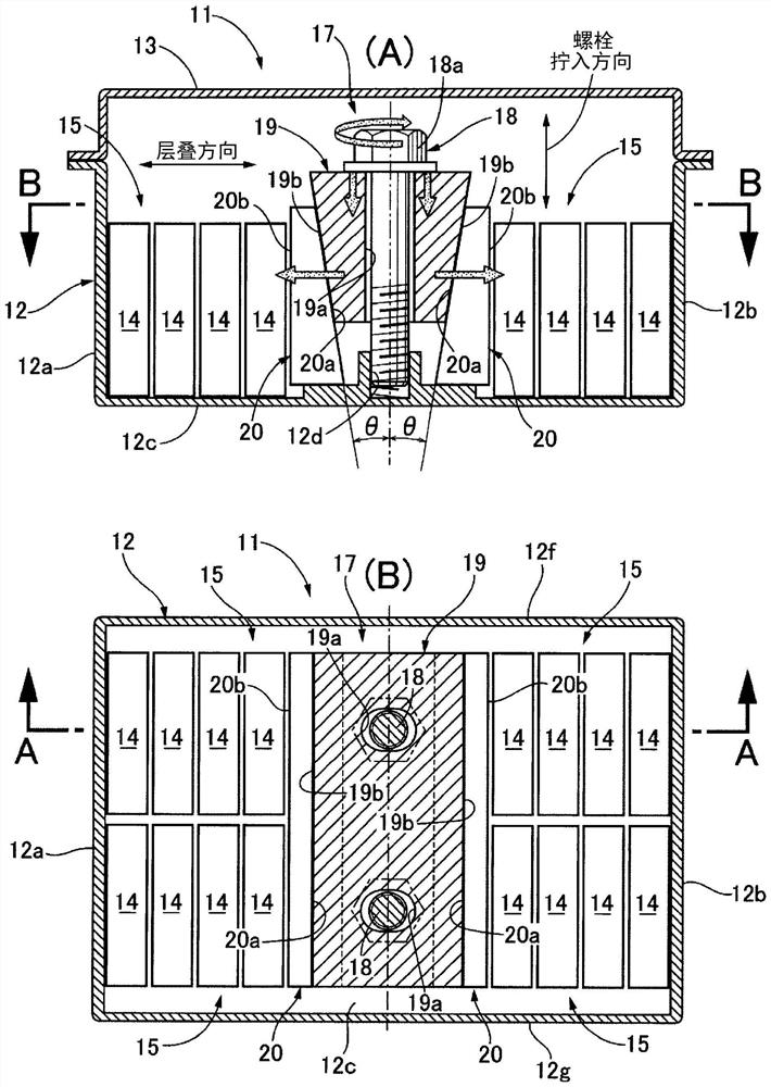
[0070] Next, based on image 3 A fourth embodiment of the present invention will be described.

[0071] In the battery package 11 of the fourth embodiment, a cell pressing mechanism 17 is arranged in the center of the battery case 12 in the stacking direction, and two end plates 20, 20 and two cell pressing mechanisms are respectively arranged on both sides of the battery case 12 in the stacking direction. Laminate 15, 15. The wedge member 19, the bolts 18, 18, and the female threaded parts 12d, 12d of the single-body pressing mechanism 17 are the same as those of the first embodiment, but end plates 20, 20 are disposed on both sides of the wedge member 19 in the stacking direction. It is different from the first embodiment.

[0072] The wedge member 19 has first abutting surfaces 19b, 19b on both sides in the stacking direction, and each end plate 20 has a first abutting surface 20a abutting on the first abutting surface 19b of the wedge member 19 and a single laminated bod...


PUM


Abstract

The battery pack (11), which comprises a battery case (12) in which a cell stack body (15) obtained by stacking a plurality of prismatic cells (14) is housed, is provided with an end plate (20) disposed on one end side of the cell stack body (15) in the stacking direction, a wedge member (19) disposed on the opposite side of the end plate (20) from the cell stack body (15), and a bolt (18) disposed in a bolt fastening direction that is orthogonal to the stacking direction and biasing the wedge member (19) toward a bottom wall (12c) of the battery case (12). First abutting surfaces (19b, 20a) on which the wedge member (19) and the end plate (20) abut one another are constituted from sloped surfaces, each sloping toward the bolt (18) in the bolt fastening direction. Thus, through a simple structure, the cell stack body (15) can be compressed strongly so as to suppress expansion of the prismatic cells (14), and furthermore, the energy density per volume can be raised while reducing the size and weight of the battery pack (11).

Description

technical field [0001] The present invention relates to a battery pack in which a cell stack in which a plurality of rectangular cells are stacked is housed inside a battery case. Background technique [0002] Patent Document 1 below discloses a technique in which a pair of end plates are further stacked at both ends of a plurality of stacked battery cells, and both ends of a pair of ladder-shaped frames arranged along the stacking direction of the battery cells are connected by bolts. The parts are bonded to a pair of end plates, whereby a compressive force is applied to a plurality of battery cells to suppress expansion, and these are integrated to form a battery module. [0003] prior art literature [0004] patent documents [0005] Patent Document 1: Japanese Patent Laid-Open No. 2012-256466 [0006] The problem to be solved by the invention [0007] However, conventional battery packs for vehicles have a structure in which a plurality of battery modules are housed ...

Claims


Application Information

Patent Timeline
Patent Type & Authority Applications(China)
IPC IPC(8): H01M2/10H01M50/209H01M50/264
CPCY02E60/10H01M2220/20H01M50/209H01M50/249H01M50/269H01M50/264H01M50/242H01M50/291
Inventor 关日出海大熊香苗
Owner HONDA MOTOR CO LTD
Why Eureka
Try Eureka