Fluidic device

a technology of fluid device and fluid volume, which is applied in the direction of flexible wall reciprocating engines, reciprocating piston engines, positive displacement engines, etc., can solve the problems of limited operating fluid volume needed for a certain stroke or pivot or rotational movement, and it is not important whether the wall of the hollow body is of single- or multi-wall design

Inactive Publication Date: 2006-08-08
GSI HELMHOLTZZENT FUR SCHWERIONENFORSCHUNG
View PDF8 Cites 61 Cited by
  • Summary
  • Abstract
  • Description
  • Claims
  • Application Information

AI Technical Summary

Benefits of technology

[0007]The hollow body is fluid-tight and at least partially in the form of a bellows. It has a fluid-tight wall and fluid admission and discharge passages. It has a predetermined direction of expansion; with the introduction of fluid, it grows essentially only in one direction which is predetermined by the bellows-like shape of the hollow body. Expansion normal to the predetermined direction is greatly limited because of the configuration of the hollow body. Also, the operating fluid volume needed for a certain stroke or pivot or rotational movements is limited by the high stiffness of the hollow body in radial that is a direction transverse to the operating direction. Since the cross-section of the drive normal to the operating direction changes only insignificantly during operation, also the actuating force can be more accurately controlled and dosed for small movements. The expansion force of the hollow body is transferred to adjacent components by way of at least two force transmission areas.
[0012]Non-stretchable in this connection for all the annular elements, walls or connections means that there is no undesired stretching. But, in accordance with the invention, a tolerable or desirable degree of stretchability of the non-stretchable components for example for a reduction of local stress peaks or to avoid damage to the fluidic drive may be provided. Particular reference is made at this point to the functions of the non-stretchable components which are provided to avoid sideward expansions of the hollow body and which ensure the guidance and predetermined movement of the hollow body and the drive elements.
[0015]In its empty state and with a thin wall and thin annular elements the bellows-like hollow body has a very short length. In this way, the fluidic drive may be used also under tight conditions between the front faces of two components which are interconnected by a joint for example in a manipulator as disclosed in DE AS 23 45 856. It is also basically suitable for the operation of pivot members over large angular areas because of the guide elements referred to earlier and the unidirectional expansion of the bellows-like hollow body.

Problems solved by technology

Expansion normal to the predetermined direction is greatly limited because of the configuration of the hollow body.
Also, the operating fluid volume needed for a certain stroke or pivot or rotational movements is limited by the high stiffness of the hollow body in radial that is a direction transverse to the operating direction.
It is unimportant whether the wall of the hollow body is of single- or multi-wall design.

Method used


Image

  • Fluidic device
  • Fluidic device
  • Fluidic device

Examples


fourth embodiment

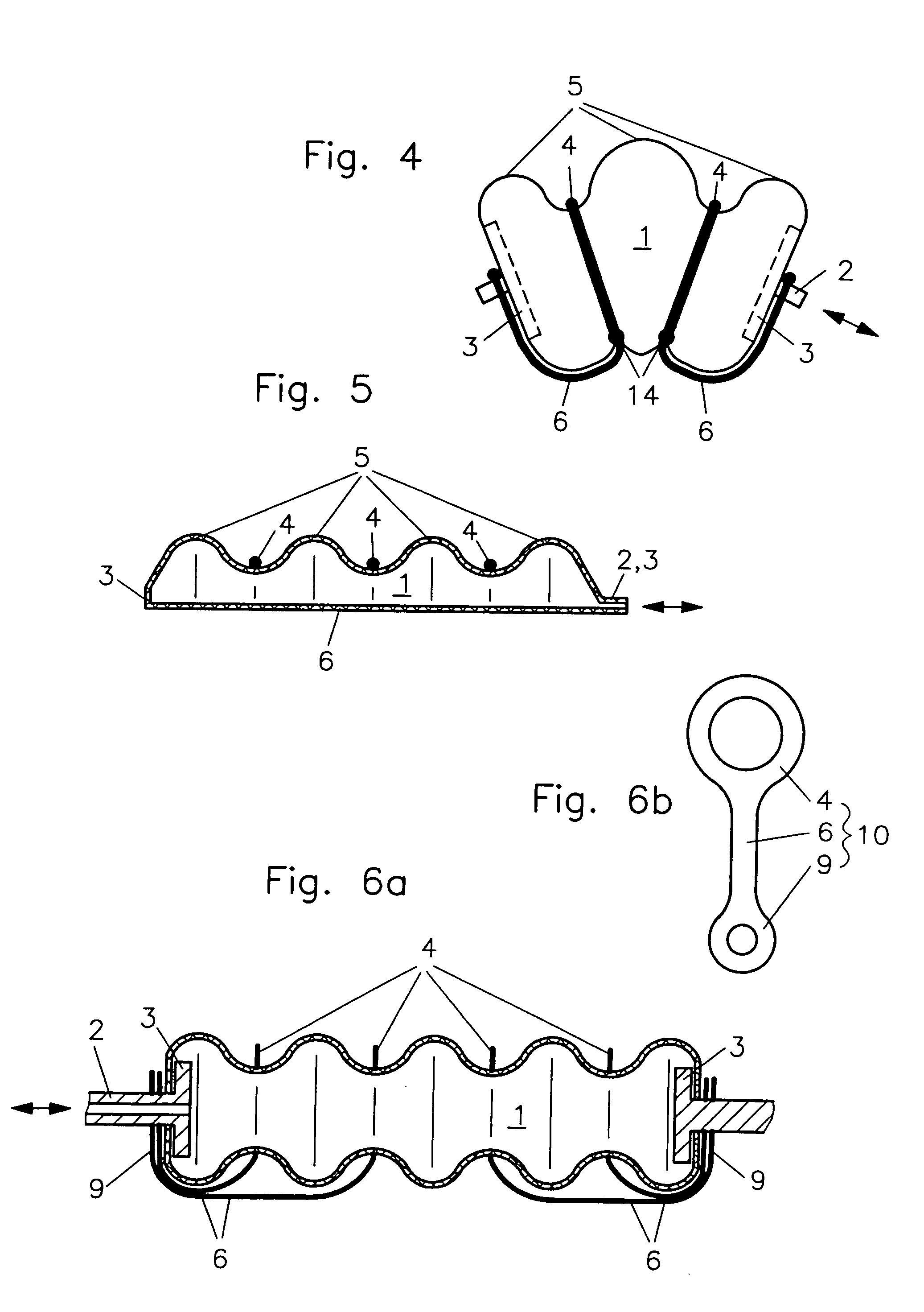
[0027]FIG. 4 shows a fourth embodiment with a connection 6 in the form of pleats interconnected at one side of the hollow body which are connected to the force transmission areas 3 in a non-elastic manner (for example by strings). In contrast to the arrangements shown in the previous figures, the connection comprises in addition to the additional components such as strings or cement, particularly non-resilient wall areas between the individual, preferably point-like, connections 14 on the pleats.

fifth embodiment

[0028]FIG. 5 shows a fifth embodiment wherein the connection and the ring elements are formed by correspondingly designed non-elastic walls. The pleats or bellows configuration of the hollow body and consequently an expandability of the hollow body exists only at one side of the hollow body (in FIG. 5 the upper half) whereas the flat area opposite the pleated wall area is formed by a non-stretchable wall and therefore represents the non-resilient connection 6.

[0029]Because of the small diameters of the supply and release duct 2 hollow bodies as shown in FIG. 5 cannot be manufactured by a single stage vulcanization process on a molded core. They are therefore manufactured for example by a two-stage molding process wherein, in a first step, the bellows-like area of the hollow body is manufactured for example from an elastomer by way of a vulcanizing process and, in a second step, the smooth or flat area consisting of an elastomer possibly with an additional non-resilient reinforcement...

sixth embodiment

[0030]In a sixth embodiment as shown in principle in FIGS. 6a and 6b, non-resilient connections 6, ring elements 4 and mounting means 9 for attaching the connections 6 to the connecting areas 3 are comprised of at least one guide component 10 of a foil material. A pattern for such a guide component 10 is shown in FIG. 6b. FIG. 6a shows the application of several such guide members to a bellows-like hollow body 1, wherein, in the arrangement shown, each pleat is provided with its own guide member which is connected to the force transmission area. Other possible versions comprise also a coupling of two or several connecting areas by way of, in each case, a single guide member. If used as a pivot drive, the connections 6 may not be provided only at one side as shown in FIG. 6, but additionally at the opposite side.

[0031]The installation of the fluidic drive on two components 12, which are interconnected by a joint 11, is shown for example in FIGS. 7a and 7b. The components 12 include e...


PUM


Abstract

In a fluidic drive for disposition between two components which are movable relative to each other comprising a hollow body with a duct for supplying fluid to, and discharging it from, the hollow body wherein the hollow body consists at least partially of a bellows structure, non-resilient ring elements extend around the hollow body in each of its pleats and a connecting structure extends at least at one side of the hollow body and interconnects the non-resilient ring elements.

Description

BACKGROUND OF THE INVENTION[0001]The invention resides in a fluidic drive disposed between two compounds which are arranged so as to be movable relative to each other and comprising a hollow body with a fluid admission and a fluid discharge line.[0002]Such drives are used for initiating translatory movements, but also pivot movements or rotational movements mainly in the area of robotics but also prosthetics. They comprise essentially at least one hydraulic or pneumatic drive element disposed between two parts which are arranged movably relative to each other. The drive elements are connected to each of the two parts by at least one force transmission area. Preferably, the drive element comprises a hollow body with an operating fluid supply and discharge line.[0003]DE-AS 23 45 856 discloses a fluidic drive in connection with a manipulator which comprises a bladder disposed at the side of a joint between two opposite force areas of two components such that an expansion of the bladder...

Claims


Application Information

Patent Timeline
Patent Type & Authority Patents(United States)
IPC IPC(8): F16J3/00F15B15/10
CPCF15B15/103
Inventor SCHULZ, STEFAN
Owner GSI HELMHOLTZZENT FUR SCHWERIONENFORSCHUNG
Why Eureka
Try Eureka