Hole punching machine for automotive parts processing using gears for precise positioning

An auto parts, precise positioning technology, applied in positioning devices, metal processing equipment, feeding devices, etc., can solve the problem of difficult to control the clamping force of the pressing block and the accuracy of positioning, affecting the punching efficiency of the punching machine and punching accuracy, etc., to achieve the effect of improving the punching effect, improving the accuracy, and increasing the range of

Active Publication Date: 2022-02-11
芜湖市夯福机械模具有限公司
View PDF0 Cites 0 Cited by
  • Summary
  • Abstract
  • Description
  • Claims
  • Application Information

AI Technical Summary

Problems solved by technology

[0003] When the existing punching machine clamps and positions the disc-shaped workpiece, most of them use the cooperation of the pressing block and the bolt to press the pressing block to the surface of the disc-shaped workpiece, and then fix the pressing block by the bolt. The bolts are manually tightened, which makes it difficult to control the clamping force and positioning accuracy of the disc-shaped workpiece by the pressing block, which in turn affects the drilling efficiency and accuracy of the punching machine for the disc-shaped workpiece.

Method used


Image

  • Hole punching machine for automotive parts processing using gears for precise positioning
  • Hole punching machine for automotive parts processing using gears for precise positioning
  • Hole punching machine for automotive parts processing using gears for precise positioning

Examples


Embodiment approach

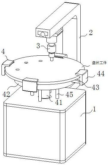
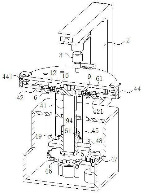
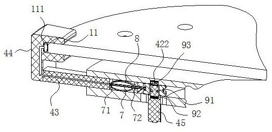
[0024] As an embodiment of the present invention, the rotating winch 6 is flexibly connected to the rotating column through a limit sliding mechanism 9; the outer wall of the support shaft is provided with a plurality of limit inserts 94; The top is provided with a plurality of limiting slots 51, and the limiting inserts 94 are slidably inserted into the plurality of limiting slots 51; the thickness of the driving gear 47 is greater than the overall thickness of the driven gear 46 and the meshing wheel 49; The bottom end of the fixed disk 42 is rotated with a rotating ring 10, and a plurality of rotating rods 45 are inserted into the rotating ring 10 through bearings;

[0025] During work, when the fixed disc 42 needs to be rotated, and then when the different positions of the disc-shaped workpiece are punched, it is necessary to rotate the capstan 6 to be disconnected from the rotating rod 45, and then it is convenient for the fixed disc 42 to rotate; Control the rotating cap...


PUM


Abstract

The invention belongs to the technical field of auto parts processing, and specifically relates to a punching machine for processing auto parts by using gears for precise positioning; it includes a chassis, a beam and a driving punching mechanism; the beam is provided with a driving punching mechanism; the main shaft is supported It is installed on the chassis through bearing rotation, and a fixed plate is installed on the top of the supporting spindle; a sliding cavity is opened inside the fixed plate, and a plurality of sliding rods are slidingly arranged in the sliding cavity; the outer ends of the multiple sliding rods are connected with snap-fit block; a plurality of rotating rods are arranged in the circumferential direction of the outer ring of the supporting spindle; a driven gear is fixed on the outer wall of the rotating cylinder, and an engaging toothed disc is fixed on the upper end of the rotating cylinder; the engaging toothed disc is located above the driven gear; multiple rotating rods Planetary gears are fixed at the bottom of the bottom, and multiple planetary gears are meshed with the meshing toothed disc; multiple engaging blocks can simultaneously perform clamping and positioning operations on the disc-shaped workpiece, thereby improving the clamping of the disc-shaped workpiece on the punching machine. Tight positioning accuracy.

Description

technical field [0001] The invention belongs to the technical field of auto parts processing, in particular to a punching machine for auto parts processing which utilizes gears for precise positioning. Background technique [0002] In the process of automobile manufacturing, various auxiliary devices need to be used. The punching device is one of the more common and widely used ones. After the production of auto parts is completed, holes are punched on the parts according to the actual use needs, so as to facilitate the subsequent installation process. Therefore, the quality of the punching device is related to the punching The precision, which in turn is related to the quality of parts and subsequent installation. [0003] When the existing punching machine clamps and positions the disc-shaped workpiece, most of them use the cooperation of the pressing block and the bolt to press the pressing block to the surface of the disc-shaped workpiece, and then fix the pressing bloc...

Claims


Application Information

Patent Timeline
IPC IPC(8): B21D28/24B21D43/00
CPCB21D28/24B21D43/003
Inventor 陶老夯陶庭富
Owner 芜湖市夯福机械模具有限公司
Why Eureka
Try Eureka