
Engine air cylinder sleeve dismounting and mounting equipment and use method thereof

A technology for engine cylinders and cylinder liners, which is applied in metal processing equipment, metal processing, manufacturing tools, etc., and can solve problems such as low disassembly efficiency, high labor intensity for workers, and cumbersome operations

Active Publication Date: 2020-10-27
ZYNP GRP ANHUI CO LTD
View PDF7 Cites 0 Cited by
  • Summary
  • Abstract
  • Description
  • Claims
  • Application Information

AI Technical Summary

Problems solved by technology

[0005] The object of the present invention is to provide a kind of engine cylinder liner dismounting equipment and its use method, to solve the existing engine cylinder liner dismounting equipment, it needs to be installed on the cover plate, and the cylinder liner is ejected through the bolt rocker, The operation is cumbersome, and workers need to repeatedly align the cylinder liner inside the end cover with the push plate, which takes a lot of time for disassembly and assembly; the existing engine cylinder liner disassembly equipment needs to manually turn the rocker to realize the cylinder liner. Take out the work, the labor intensity of the workers is high, and the disassembly efficiency is low

Method used


Image

  • Engine air cylinder sleeve dismounting and mounting equipment and use method thereof
  • Engine air cylinder sleeve dismounting and mounting equipment and use method thereof
  • Engine air cylinder sleeve dismounting and mounting equipment and use method thereof

Examples


Embodiment Construction

[0027] The technical solutions of the present invention will be clearly and completely described below in conjunction with the embodiments. Apparently, the described embodiments are only some of the embodiments of the present invention, not all of them. Based on the embodiments of the present invention, all other embodiments obtained by persons of ordinary skill in the art without creative efforts fall within the protection scope of the present invention.

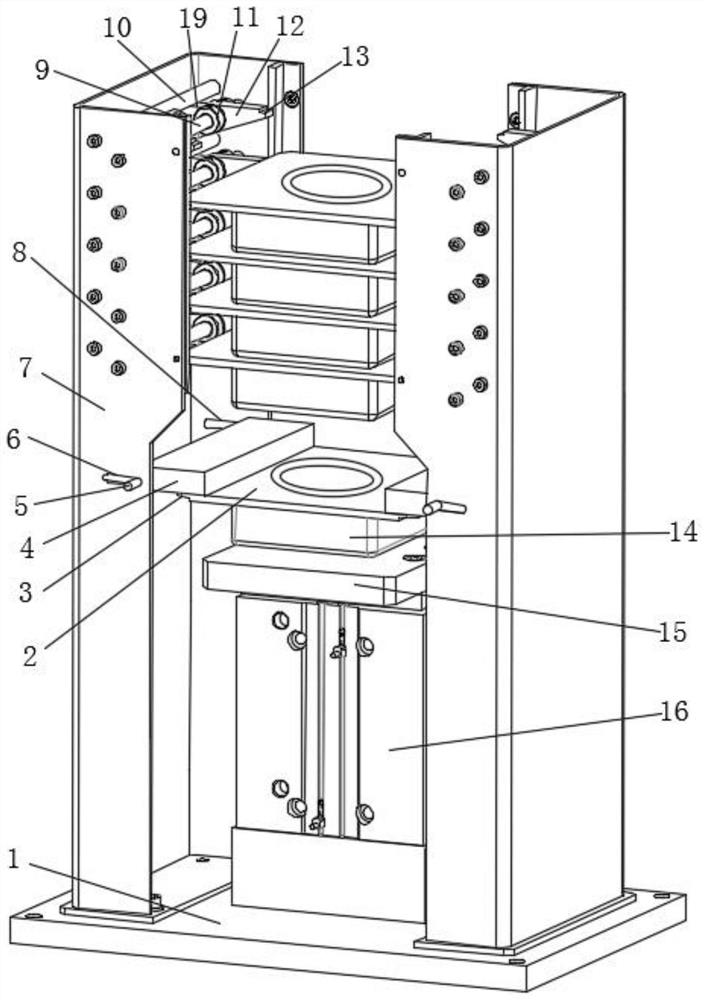
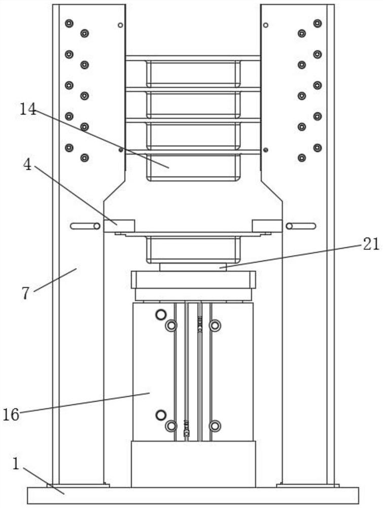
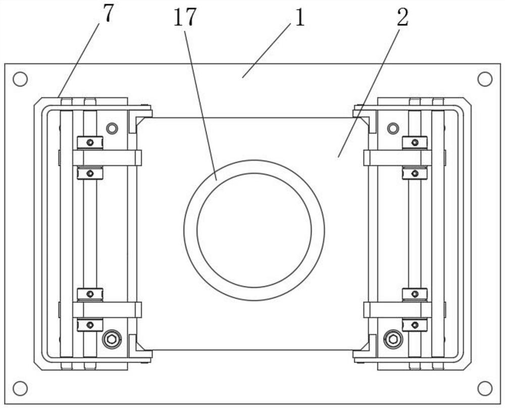
[0028] like Figure 1-6 As shown, a kind of engine cylinder liner dismounting equipment comprises base plate 1, and the two ends of the top of described base plate 1 are respectively provided with support plates 7, and two support plates 7 are perpendicular to the top surface of base plate 1 respectively, and two support plates 7 A hydraulic cylinder 16 is arranged on the bottom plate 1 between them, and a piston rod is arranged inside the hydraulic cylinder 16. The top of the piston rod is fixedly connected with a top bloc...


PUM


Abstract

The invention discloses an engine air cylinder sleeve dismounting and mounting equipment. The engine air cylinder sleeve dismounting and mounting equipment comprises a bottom plate, supporting platesare arranged at the two ends of the top of the bottom plate correspondingly and are perpendicular to the top face of the bottom plate, a hydraulic cylinder is arranged at the position, between the twosupporting plates, of the bottom plate, a second clamping groove is formed in one end of the top of each placing block and matched with a first clamping groove in one side of an end cover, fixing work of the end cover is achieved, the other end cover is taken out to downwards press the end cover below the end cover, so that the four placing blocks correspondingly drive a rotating shaft to rotate,a spring in a shaft sleeve is deformed, the end cover below the shaft sleeve is moved to the next layer of placing block, and the operation is repeated to realize the mounting and placing of a plurality of end covers. The hydraulic cylinder controls a piston rod in the hydraulic cylinder to move upwards, the piston rod pushes an ejection block to move upwards, the end cover located on the lowermost layer falls onto a push plate, the feeding effect is achieved, workers do not need to center the air cylinder sleeve in the end cover and the push plate repeatedly, and the dismounting and mountingtime is saved.

Description

technical field [0001] The invention relates to the field of engine cylinder liner disassembly equipment, in particular to an engine cylinder liner disassembly equipment and a use method thereof. Background technique [0002] The engine cylinder liner needs to be disassembled and assembled during use. The traditional cylinder liner dismantling equipment is cumbersome and inconvenient to use. [0003] The existing engine cylinder liner disassembly and assembly equipment needs to be installed on the cover plate, and the cylinder liner is ejected through the bolt rocker. The operation is cumbersome and requires workers to repeatedly align the cylinder liner inside the end cover with the push plate. It takes a lot of time for disassembly and assembly; the existing engine cylinder liner disassembly and assembly equipment needs to manually rotate the rocker to realize the removal of the cylinder liner, the labor intensity of workers is high, and the disassembly and assembly effici...

Claims


Application Information

Patent Timeline
IPC IPC(8): B23P19/027B23P19/00
CPCB23P19/001B23P19/027
Inventor 王传超储建华刘艳林
Owner ZYNP GRP ANHUI CO LTD
Learn More