
Niobium alloy cast iron engine cylinder sleeve and production process thereof

A technology for engine cylinders and production processes, which is applied to engine components, machines/engines, metal processing equipment, etc., and can solve problems such as reducing the installation and fixing efficiency of engine cylinder liner, moving up and down, and being unable to place them.

Inactive Publication Date: 2020-10-27
ZYNP GRP ANHUI CO LTD
View PDF6 Cites 1 Cited by
  • Summary
  • Abstract
  • Description
  • Claims
  • Application Information

AI Technical Summary

Problems solved by technology

[0004] The object of the present invention is to provide a kind of niobium alloy cast iron engine cylinder liner and its production process, to solve the existing engine cylinder liner production and processing process, when carrying out the loading work, the material loading is relatively complicated, there are differences between the angle position of the engine cylinder liner The position of the lifting plate does not correspond to the problem that it cannot be placed, which reduces the installation and fixing efficiency of the engine cylinder liner; in the production and processing process of the existing engine cylinder liner, the two sides of the engine cylinder liner are fixed by the splints on both sides, and the direction of the tree branch is fixed. When plugging and unplugging, it is easy to move up and down, the fixation is not firm, it is not convenient to process the engine cylinder liner, and the stability of the engine cylinder liner on the lifting plate is poor; in the existing production and processing process of the engine cylinder liner, the engine cylinder liner of different sizes cannot be realized. The fixed work of the cylinder liner, the problem that the application range of the device is small

Method used


Image

  • Niobium alloy cast iron engine cylinder sleeve and production process thereof
  • Niobium alloy cast iron engine cylinder sleeve and production process thereof
  • Niobium alloy cast iron engine cylinder sleeve and production process thereof

Examples


Embodiment Construction

[0026] The technical solutions of the present invention will be clearly and completely described below in conjunction with the embodiments. Apparently, the described embodiments are only some of the embodiments of the present invention, not all of them. Based on the embodiments of the present invention, all other embodiments obtained by persons of ordinary skill in the art without creative efforts fall within the protection scope of the present invention.

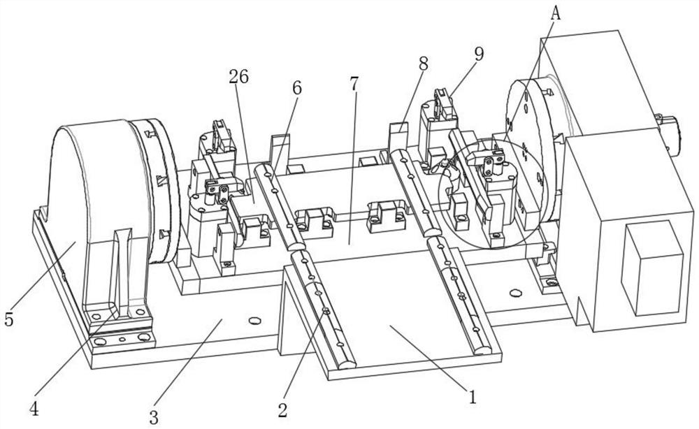
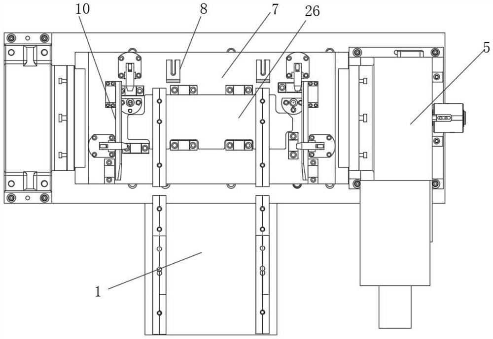
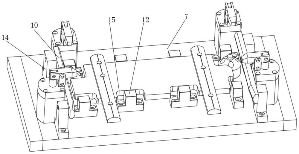
[0027] Such as Figure 1-5 Shown, a kind of niobium alloy cast iron engine cylinder liner, this engine cylinder liner adopts niobium alloy cast iron to make, the production technology of this niobium alloy cast iron engine cylinder liner specifically comprises the following steps:

[0028] Step 1: When loading materials, place the engine cylinder liner on the two first slide rails 2 on the transition plate 1, adjust the position and angle of the engine cylinder liner on the transition plate 1, and then push the engine cylin...


PUM


Abstract

The invention discloses a niobium alloy cast iron engine cylinder sleeve. The engine cylinder sleeve is made of niobium alloy cast iron. The engine cylinder sleeve is placed on two first sliding railson a transition plate, the position and the angle of the engine cylinder sleeve are adjusted on the transition plate, then the engine cylinder sleeve is pushed to move to two second sliding rails ona lifting plate, and feeding work is completed; second hydraulic cylinders control second piston rods inside the second hydraulic cylinders to move towards the outer sides of cylinder bodies, and thesecond piston rods push inserting rods to move upwards; due to the fact that second rotating shafts and third rotating shafts are arranged inside through holes in the two ends of adjusting plates correspondingly, the inserting rods push one ends of pressing rods to move upwards and the other ends of the pressing rods to move downwards, then the engine cylinder sleeve on the lifting plate is pressed; and four pressing devices work at the same time, the four corner positions of the engine cylinder sleeve are fixed, and then machining of the engine cylinder sleeve is achieved.

Description

technical field [0001] The invention relates to the field of engine cylinder liner processing equipment, in particular to a niobium alloy cast iron engine cylinder liner and a production process thereof. Background technique [0002] The inner surface of the cylinder liner is directly affected by high-temperature and high-pressure gas, and always has high-speed sliding friction with the piston ring and piston skirt. The surface is in contact with cooling water, and severe thermal stress is generated under a large temperature difference, which is corroded by cooling water. The side thrust of the piston to the cylinder liner not only intensifies the friction on its inner surface, but also makes it bend. The piston also hits the cylinder liner when the side thrust changes direction. In addition, it is subjected to a large installation preload. When the existing engine cylinder liner is produced and processed, it needs to be fixed first. [0003] In the existing production a...

Claims


Application Information

Patent Timeline
IPC IPC(8): B25B11/00B23Q3/08F02F1/00
CPCB25B11/00B23Q3/082F02F1/004
Inventor 储建华江诚王传超
Owner ZYNP GRP ANHUI CO LTD
Learn More