Bearing turnover mechanism of fully automatic rotor assembly equipment

A technology of rotor assembly and turning mechanism, which is applied in the manufacture of motor generators, electromechanical devices, electric components, etc., and can solve problems such as bearing surface damage

Inactive Publication Date: 2020-10-27
上海斐奥自动化科技有限公司
View PDF14 Cites 4 Cited by
  • Summary
  • Abstract
  • Description
  • Claims
  • Application Information

AI Technical Summary

Problems solved by technology

[0004] The purpose of the present invention is to provide a fully automatic rotor assembly equipment bearing turning mechanism to solve the problem that the clamping parts of the ex

Method used


Image

  • Bearing turnover mechanism of fully automatic rotor assembly equipment
  • Bearing turnover mechanism of fully automatic rotor assembly equipment
  • Bearing turnover mechanism of fully automatic rotor assembly equipment

Examples


Embodiment Construction

[0026] The following will clearly and completely describe the technical solutions in the embodiments of the present invention with reference to the accompanying drawings in the embodiments of the present invention. Obviously, the described embodiments are only some, not all, embodiments of the present invention. Based on the embodiments of the present invention, all other embodiments obtained by persons of ordinary skill in the art without making creative efforts belong to the protection scope of the present invention.

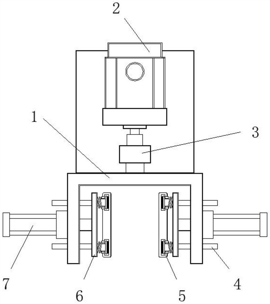
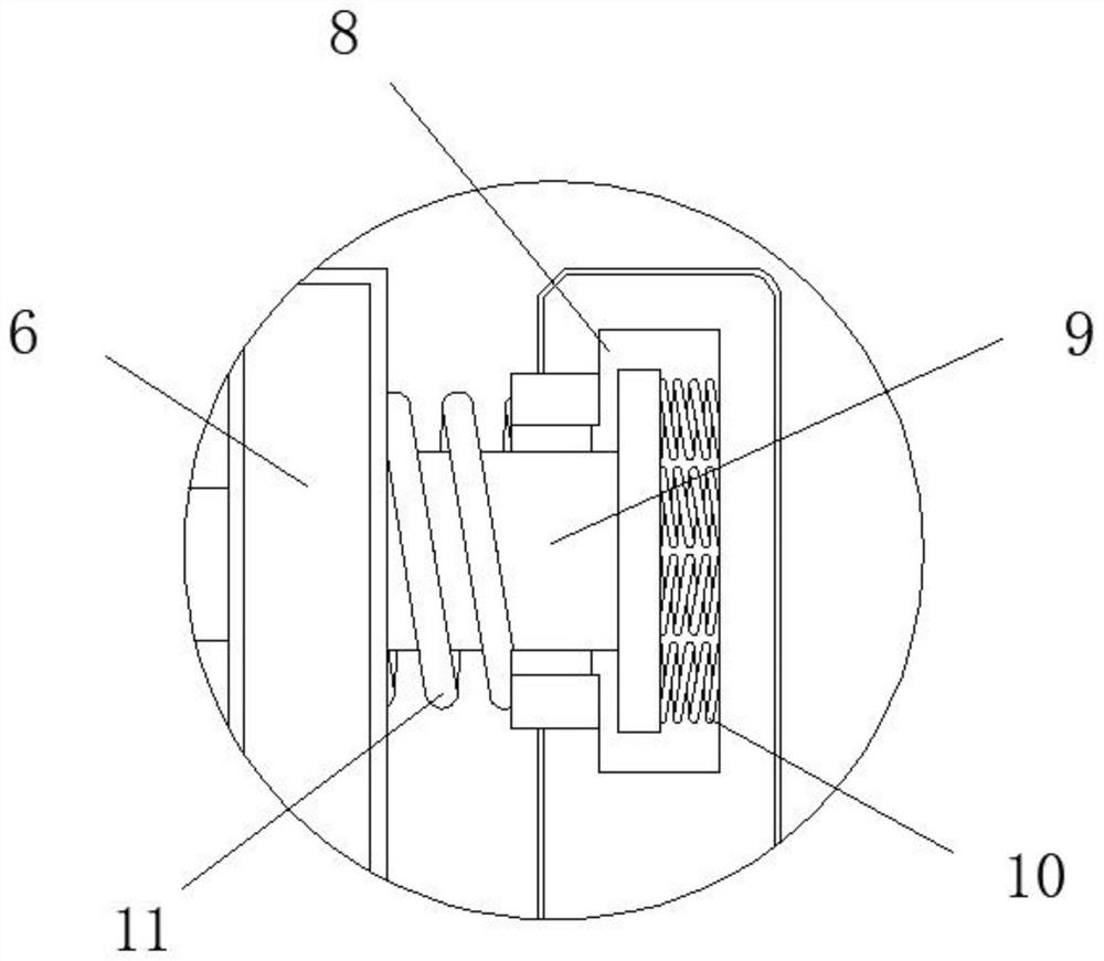
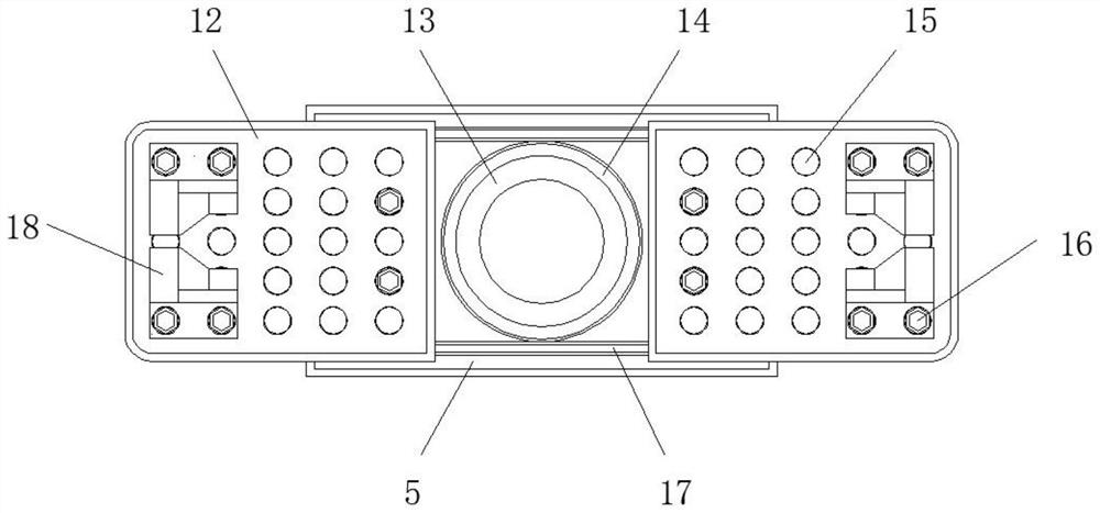
[0027] see Figure 1-6 , the present invention provides a technical solution: a fully automatic rotor assembly equipment bearing turning mechanism, including a fixed frame 1, a motor 2, a bearing seat 3, a hydraulic pump 7, a base plate 6 and a positioning column 4, and a pair of base plates 6 are provided in total. They are respectively arranged on both sides inside the fixed frame 1, the external hydraulic pump 7 on both sides of the fixed frame 1 is fixedly...


PUM


Abstract

The invention discloses a bearing turnover mechanism of fully automatic rotor assembly equipment. The mechanism comprises a fixing frame, a motor, a bearing seat, a hydraulic pump, a base plate and apositioning column, wherein the outer surface of the base plate is provided with a fixing clamping plate, a fixing groove is provided on the end surface of the fixing clamping plate adjacent to the base plate, the end surface of the base plate adjacent to the fixing clamping plate is fixedly connected with a fixing column, the end of the fixing column is fixed inside the fixing groove, the end surface of the fixing column and the inner wall of the fixing groove are fixedly connected with an inner spring, an outer spring is provided on the outside of the fixing column, one end of the outer spring is fixed on the inner surface of the fixing clamping plate, and the other end of the outer spring is fixed on the outer surface of the base plate. Through the designed fixing column, the inner spring and the outer spring, the fixing clamping plate produces a buffer for the certain deformation of the inner spring and the outer spring during the bearing clamping process, and the resilient force of the springs ensures the clamping of the bearing by the clamping part.

Description

technical field [0001] The invention belongs to the technical field of rotor assembly, and in particular relates to a bearing turning mechanism of automatic rotor assembly equipment. Background technique [0002] Rotors are mostly the main rotating parts in power machinery and working machinery, such as motors or the rotating parts of some rotary machines. The rotors of motors are generally composed of iron cores wound with coils, slip rings, fan blades, etc. In micro precision motors In the field of production, it is necessary to install precision bearings at both ends of the rotor. Whether the bearings are installed well or not will affect the accuracy, life and performance of the bearings. At present, the bearing turning mechanisms that appear on the market still have various deficiencies. , cannot meet the needs of production and life. [0003] For example, in the existing bearing turning mechanism, the clamping part usually exerts direct pressure on the bearing, which ...

Claims


Application Information

Patent Timeline
IPC IPC(8): B25B27/06B25B11/02H02K15/00
CPCB25B11/005B25B11/02B25B27/06H02K15/00
Inventor 李渊
Owner 上海斐奥自动化科技有限公司
Why Eureka
Try Eureka