Series helical spring type step energy storage mechanism and use method thereof

A technology of a coil spring and an energy storage mechanism, which is applied in the field of spring energy storage, can solve the problems such as the inability to meet the requirements of vehicle riding comfort and handling stability, and the inability to meet the suspension stroke and static deflection at the same time.

Pending Publication Date: 2020-10-27
江苏倍适特汽车科技有限公司
View PDF0 Cites 2 Cited by
  • Summary
  • Abstract
  • Description
  • Claims
  • Application Information

AI Technical Summary

Problems solved by technology

[0004] The technical problem to be solved by this invention is that the existing spring energy storage mechanism for automobile suspension adopts a single helical spring structure, and because the stiffness of the helical spring is linearly constant, the spring with constant stiffness often c

Method used


Image

  • Series helical spring type step energy storage mechanism and use method thereof
  • Series helical spring type step energy storage mechanism and use method thereof
  • Series helical spring type step energy storage mechanism and use method thereof

Examples


Embodiment 1

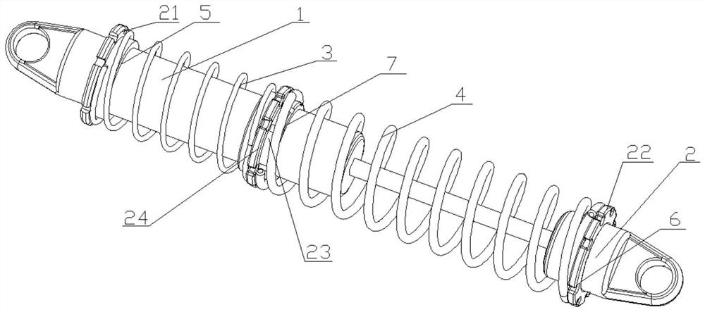
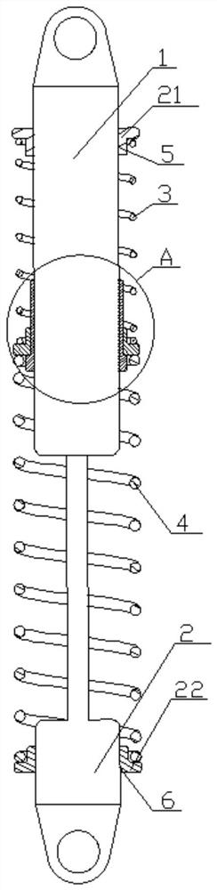
[0052] Such as Figure 1-10 As shown, a series coil spring type stepped energy storage mechanism includes a cylinder body 1 and a telescopic part 2. One end of the telescopic part 2 is inserted into the cylinder body 1, and the telescopic part 2 can The axis is telescopic, and it also includes a first coil spring 3, a second coil spring 4, a first installation assembly 21, a second installation assembly 22, and an intermediate adjustment assembly. The first installation assembly 21 and the intermediate adjustment assembly are all installed on the barrel On the body 1, the first installation component is arranged on the side of the telescopic part 2 away from the cylinder body 1, and the intermediate adjustment component is located between the first installation component 21 and the second installation component 22, The first coil spring 3 is sheathed on the cylinder body 1, and the first coil spring 3 is located between the first mounting assembly 21 and the intermediate adjus...

Embodiment 2

[0054] Such as figure 1 , figure 2 , Figure 4 As shown, this embodiment is basically the same as Embodiment 1, the difference is that a first threaded hole 5 is provided in the middle of the first mounting assembly 21, and a threaded hole 5 is provided on the barrel 1 to match the first threaded hole 5. The first mounting assembly 21 is mounted on the cylinder body 1 through screw fit, the middle part of the second mounting assembly 22 is provided with a second threaded hole 6, and the end of the telescopic part 2 is away from the cylinder body 1 Threads that cooperate with the second threaded hole 6 are provided, and the second mounting assembly 22 is mounted on the side of the telescopic part 2 away from the cylinder body 1 through thread fit.

Embodiment 3

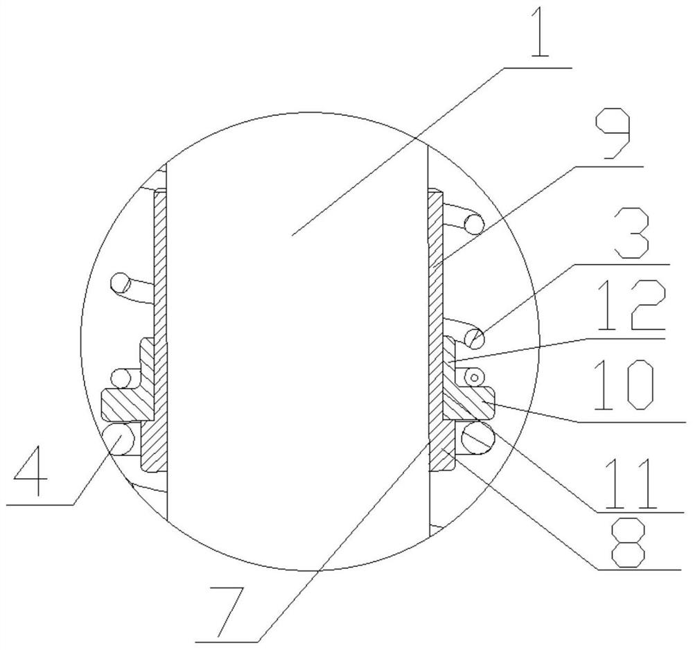
[0056] Such as Figure 1-3 As shown, this embodiment is basically the same as Embodiment 2, the difference is that the intermediate adjustment assembly includes a third mount assembly 23 and a fourth mount assembly 24, and the third mount assembly 23 is provided with a penetrating The third threaded hole 7, the barrel body 1 is provided with threads, the third mounting seat assembly 23 is mounted on the barrel body 1 through the third threaded hole 7, and the fourth mounting seat assembly 24 sets It is arranged on the cylinder body 1 , and the fourth mounting seat component 24 is located on the side close to the third mounting seat component 23 of the first coil spring 3 and the second coil spring 4 with a smaller maximum load.


PUM


Abstract

The invention discloses a series helical spring type step energy storage mechanism. A first mounting assembly and a middle adjusting assembly are both mounted on a barrel body, the first mounting assembly is arranged on the side, away from the barrel body, of a telescopic part, a first helical spring is arranged on the barrel body in a sleeving mode and positioned between the first mounting assembly and the middle adjusting assembly, a second helical spring is arranged on the telescopic part in a sleeving mode and positioned between the middle adjusting assembly and the second installation assembly, the maximum load of the first helical spring is different from the maximum load of the second helical spring, the middle adjusting assembly can limit the one, with the smaller maximum load, ofthe first helical spring and the second helical spring to move towards the middle adjusting assembly, and the one, with larger maximum load, of the first helical spring and the second helical spring can push the middle adjusting assembly to move to compress the one, with smaller maximum load, of the first helical spring and the second helical spring. The elastic stiffness of the energy storage mechanism can be changed in a stepped manner.

Description

technical field [0001] The invention relates to the technical field of spring energy storage, in particular to a cascade helical spring type stepped energy storage mechanism. Background technique [0002] With the improvement of people's living standards, driving vehicles has become the preferred way of travel for people today. For passenger vehicles, people often put forward higher requirements for ride comfort, and the ride comfort of the vehicle is largely determined by the stiffness of the elastic components of the chassis. Currently, the spring elements of passenger vehicles are mainly helical springs, whose stiffness is generally linear, that is, the stiffness is constant. Springs with constant stiffness often cannot meet the requirements of the vehicle chassis suspension system for ground clearance, suspension travel, static deflection, etc., and thus cannot meet the vehicle's requirements for ride comfort and handling stability. Most of the working conditions of th...

Claims


Application Information

Patent Timeline
IPC IPC(8): F16F13/00F16F7/116F16F9/04F16F9/32B60G11/14
CPCB60G11/14F16F7/116F16F9/0454F16F9/3207F16F13/00
Inventor 崔峰
Owner 江苏倍适特汽车科技有限公司
Why Eureka
Try Eureka