
Seal rotary ball valve with anti-loose press ring and valve seat capable of floating in single direction

A technology of rotary ball valve and valve seat, which is applied in the direction of the cock including the cut-off device, the operation/release device of the valve, and the details of the valve, which can solve the problems of large shape, two-way sealing, and difficulty in manufacturing

Pending Publication Date: 2020-10-27
ZHENGZHOU ALDU VALVE CO LTD
View PDF7 Cites 0 Cited by
  • Summary
  • Abstract
  • Description
  • Claims
  • Application Information

AI Technical Summary

Problems solved by technology

Traditionally used globe valves, gate valves, ball valves and butterfly valves, these types of valves inevitably have one or more of the disadvantages of being unable to seal in two directions, difficult to manufacture, and large in shape. Therefore, a valve that can seal in two directions and is easy to manufacture It is necessary to have a sealed rotary ball valve with a loosening pressure ring and a valve seat that can float in one direction

Method used


Image

  • Seal rotary ball valve with anti-loose press ring and valve seat capable of floating in single direction
  • Seal rotary ball valve with anti-loose press ring and valve seat capable of floating in single direction

Examples


Embodiment 1

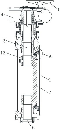
[0018] Such as figure 1 with 2 As shown, the present invention includes a valve body 1 and a valve plate 2, the valve plate 2 is located inside the valve body 1, a valve stem 3 is installed inside the valve body 1, and a driving device 4 is installed on the upper part of the valve body 1 , the top of the driving device 4 is equipped with a handwheel 5, the upper end of the valve stem 3 is connected to the driving device 4, the lower end of the valve stem 3 is connected to the upper end of the valve plate 2, and the bottom end of the valve body 1 A sealing base 6 is fixedly installed;

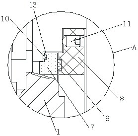
[0019] A valve seat 7 is arranged inside the valve body 1, and the valve seat 7 is located on the top of the valve plate 2. A pressure ring 8 is embedded in one side of the valve body 1, and the pressure ring 8 is located on the top of the valve seat 7. On the outside, the side of the valve seat 7 close to the pressure ring 8 is fixedly connected with a first sealing ring 9, and the first seal...

Embodiment 2

[0022] Such as figure 1 with 2 As shown, the present invention includes a valve body 1 and a valve plate 2, the valve plate 2 is located inside the valve body 1, a valve stem 3 is installed inside the valve body 1, and a driving device 4 is installed on the upper part of the valve body 1 , the top of the driving device 4 is equipped with a handwheel 5, the upper end of the valve stem 3 is connected to the driving device 4, the lower end of the valve stem 3 is connected to the upper end of the valve plate 2, and the bottom end of the valve body 1 A sealing base 6 is fixedly installed;

[0023] A valve seat 7 is arranged inside the valve body 1, and the valve seat 7 is located on the top of the valve plate 2. A pressure ring 8 is embedded in one side of the valve body 1, and the pressure ring 8 is located on the top of the valve seat 7. On the outside, the side of the valve seat 7 close to the pressure ring 8 is fixedly connected with a first sealing ring 9, and the first seal...


PUM


Abstract

The invention relates to a seal rotary ball valve with an anti-loose press ring and a valve seat capable of floating in a single direction. The seal rotary ball valve comprises a valve body and a valve plate. The valve plate is located in the valve body, a valve rod is installed in the valve body, a driving device is installed on the upper portion of the valve body, and a hand wheel is installed on the top end of the driving device. The upper end of the valve rod is in transmission connection with the driving device, the lower end of the valve rod is connected with the upper end of the valve plate, and the bottom end of the valve body is fixedly provided with a seal base. The valve seat is arranged in the valve body and located on the top of the valve plate, and the press ring is embeddedin one side of the valve body and located on the outer side of the valve seat. According to the seal rotary ball valve, through cooperation arrangement of the valve seat, the press ring, a first sealblock, a second seal block and a locking screw, dual-direction seal between the valve body and the valve plate can be achieved, a spline housing is welded to the valve plate, so that the valve rod isconnected with the valve plate through the spline housing, and accordingly the rotary ball valve is more easily manufactured.

Description

technical field [0001] The invention belongs to the technical field of sealed rotary ball valves, in particular to a sealed rotary ball valve with an anti-loosening pressure ring and a valve seat that can float in one direction. Background technique [0002] Rotary ball valves are mainly used in water supply pipelines in industries such as petroleum, chemical industry, municipal engineering, drinking water engineering, and process pipelines in which a part of the medium is liquid. They are used to cut off and adjust the medium in the pipeline. And the functions and advantages of globe valve, small size, light weight, reliable operation, can manufacture extra-large or super-large-diameter valves. Traditionally used globe valves, gate valves, ball valves and butterfly valves, these types of valves inevitably have one or more of the disadvantages of being unable to seal in two directions, difficult to manufacture, and large in shape. Therefore, a valve that can seal in two dire...

Claims


Application Information

Patent Timeline
Patent Type & Authority Applications(China)
IPC IPC(8): F16K5/06F16K5/20F16K31/60
CPCF16K5/0626F16K5/0647F16K5/0668F16K5/205F16K31/60
Inventor 王帅
Owner ZHENGZHOU ALDU VALVE CO LTD
Learn More