A Rotary Sealing Structure Capable of Two-way Sealing

A rotary sealing and two-way sealing technology, which is applied to engine sealing, engine components, mechanical equipment, etc., can solve problems such as narrow working temperature range, high lubricant dependence, and inability to balance high and low temperature resistance, and achieve a wide applicable temperature range , Lubrication conditions are low, and the effect of reducing frictional heat

Active Publication Date: 2017-12-15
CHINA NORTH VEHICLE RES INST
View PDF5 Cites 0 Cited by
  • Summary
  • Abstract
  • Description
  • Claims
  • Application Information

AI Technical Summary

Problems solved by technology

[0003] The traditional rotary seal structure is usually a rubber sealing lip, which is combined with a common spring device to provide pre-tightening force, so that the rubber sealing lip is tightly attached to the rotating shaft to form a sealing surface and realize the rotary sealing function. The sealing structure mainly has the following deficiencies: ① It is difficult to achieve two-way sealing in a small installation size, such as sealing lubricating oil on one side and sealing pressure gas on the other side
In order to realize two-way sealing, it is necessary to add another rubber sealing lip to be arranged in reverse, so that the installation space requirement of the seal is greatly increased. In the occasions where the space is small and two-way rotary sealing is required, traditional rubber rotary seals are difficult to use
②Short service life
The traditional rubber rotary seal is pre-tightened by a spring, so that the rubber sealing lip and the sealing shaft are in close contact. The rotating shaft is usually made of metal material. Due to the high friction between the rubber material and the metal material, during the rotation of the shaft In the process, the rubber sealing lip will be greatly worn, which will affect the service life of the rotary seal
③ Narrow working temperature range
Due to the poor high and low temperature resistance of rubber materials, and the high and low temperature resistance cannot be balanced, traditional rubber seals are not suitable for applications with wide temperature ranges.
④ Traditional rubber seals have high requirements for lubrication
Therefore, traditional rubber seals are highly dependent on lubricants

Method used


Image

  • A Rotary Sealing Structure Capable of Two-way Sealing
  • A Rotary Sealing Structure Capable of Two-way Sealing
  • A Rotary Sealing Structure Capable of Two-way Sealing

Examples


Embodiment 1

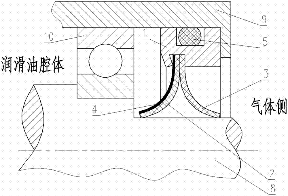
[0042] This embodiment provides an installation structure of the rotary sealing structure. The partial section diagram of the installation is attached image 3 As shown, the process of function realization is as follows:

[0043] The outer surface of the base body 1 is provided with an annular groove, and the O-ring 5 is installed in the annular groove.

[0044] The base body 1 is mounted on the inner surface of the end cap 9 without relative rotation between them, and the base body 1 and the end cap 9 are statically sealed through the O-ring 5 .

[0045] The inner surface of the base 1 is provided with an annular groove, and the rebound device 4 and the sealing lip 2 and the sealing lip 3 are pressed and installed in the annular groove on the upper inner surface of the base 1. Under moderate compression force, the connection between them is airtight.

[0046] The rotating shaft 8 is supported and positioned with the end cover 9 through the bearing 10 . After the installat...

Embodiment 2

[0050] This embodiment provides a combined structure in which two rotary seal structures are used at the same time, and is especially suitable for rotary seals that separate air passages in mechanical structures. The partial sectional view of the installation is attached Figure 4 As shown, the process of function realization is as follows:

[0051] as attached Figure 4 As shown: the base body 11 can be regarded as an extended deformation of the base body 1, and there are two annular grooves on the left and right sides of the outer surface of the base body 11, and the O-rings 5 ​​are installed in the annular grooves.

[0052] The base body 11 is installed on the inner surface of the rotating body 14 , achieves a static seal with the rotating body 14 through the O-ring 5 , and rotates together with the rotating body 14 .

[0053] There are two annular grooves on the left and right sides of the inner surface of the base body 11, and the sealing lip 2, the sealing lip 3 and th...

Embodiment 3

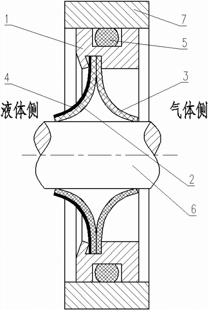
[0060] This embodiment provides a rotary sealing structure, such as figure 1 As shown, the rotary sealing structure includes: a base body 1 , a first sealing lip 2 , a second sealing lip 3 , a rebound device 4 , and an O-ring 5 .

[0061] The outer surface of the base 1 is provided with an annular groove, and the O-ring 5 is installed in the annular groove on the upper outer surface of the base 1 .

[0062] The inner surface of the base body 1 is also provided with an annular groove, the rebound device 4 is installed on one side of the sealing lip 2, the rebound device 4 and the sealing lip 2, the sealing lip 3 It is installed in the annular groove on the upper inner surface of the base body 1, and the connection between them is sealed, so that gas and liquid cannot pass through the rebound device 4, the sealing lip 2, and the sealing lip 3 connection with the substrate 1.

[0063] The sealing lip 2 and the sealing lip 3 are circular thin slices, the inner diameters of the s...


PUM


Abstract

The invention belongs to the technical field of rotary sealing and particularly relates to a rotary sealing structure with a bidirectional sealing function. The rotary sealing structure with the bidirectional sealing function is widely applied to sealing of liquid and gas, moving relative to shafts, in various mechanical structures. The rotary sealing structure is used for creating a sealing relation between a mounting body and the sealing shaft, and comprises a base body of a ring structure, a first sealing lip, a second sealing lip, a springback device and an O-shaped ring. Compared with the prior art, the rotary sealing structure has a small mounting dimension. As being simple circular ring sheets, the two sealing lips can be mounted in a small space, bidirectional sealing is realized, and accordingly the space dimension of the rotary sealing structure is more compact.

Description

technical field [0001] The invention belongs to the technical field of rotary seals, and in particular relates to a two-way sealed rotary seal structure, which is widely used in various mechanical structures for liquid and gas seals that rotate relative to shafts. Background technique [0002] The rotary seal structure is a common part in mechanical parts and is widely used in various operating mechanical structures. With the modern design level of mechanical structures and the progress of manufacturing technology, the functions of various mechanical structures are gradually increasing, and the volume is gradually decreasing, and the requirements for the rotary seals are gradually increasing. The installation space of the rotary seal is greatly compressed, but the requirements for the service life and working temperature of the rotary seal are relatively increased. In many occasions, it is also necessary for the rotary seal to achieve bidirectional sealing in a small instal...

Claims


Application Information

Patent Timeline
Patent Type & Authority Patents(China)
IPC IPC(8): F16J15/3232F16J15/3284F16J15/3212F16J15/3268
CPCF16J15/3212F16J15/3232F16J15/3268F16J15/3284
Inventor 周文杰雷强顺刘海涛张宏超闫智洲尹君胜徐晓曦范婧
Owner CHINA NORTH VEHICLE RES INST
Why Eureka
Try Eureka