Trap
A technology of water separator and main flow pipe, applied in the field of water separator with new structure, can solve the problems of fixed size of water separator, blocked flow channel, unfavorable integration applicability of water separation device layout and system volume power density, etc. The effect of high adaptability of layout integration, avoidance of flow channel blockage, and good water separation efficiency
- Summary
- Abstract
- Description
- Claims
- Application Information
AI Technical Summary
Problems solved by technology
Method used
Image
Examples
no. 1 Embodiment
[0071] The first specific embodiment of the present invention provides a water separator.
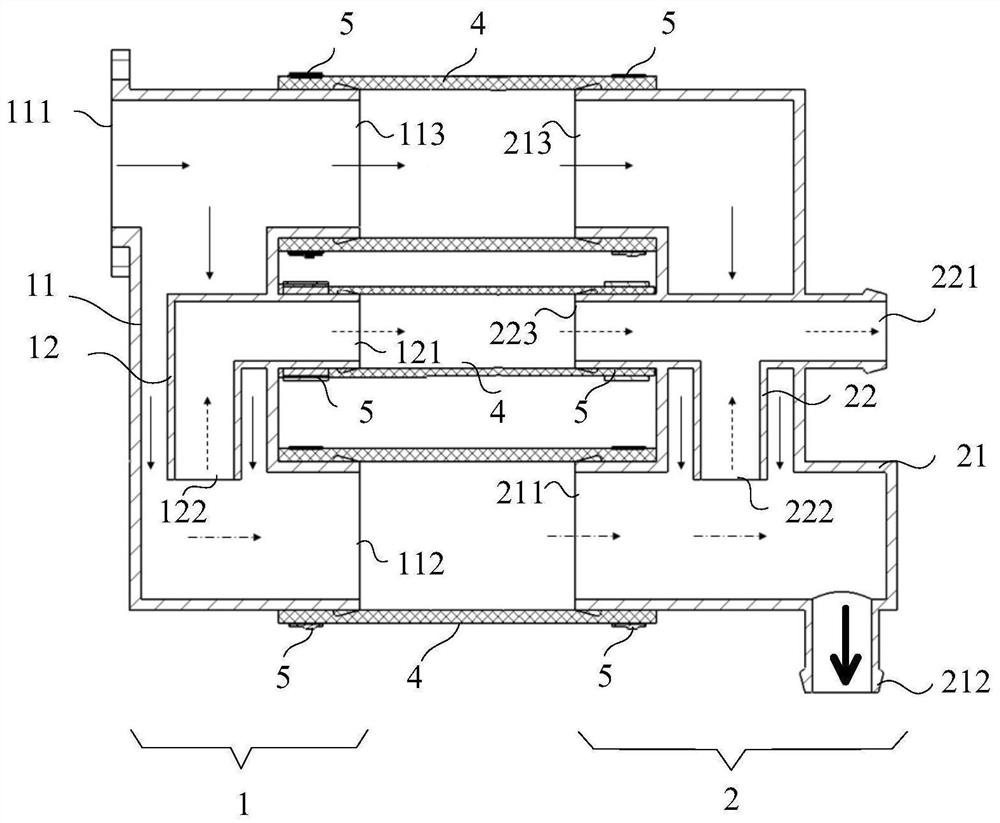
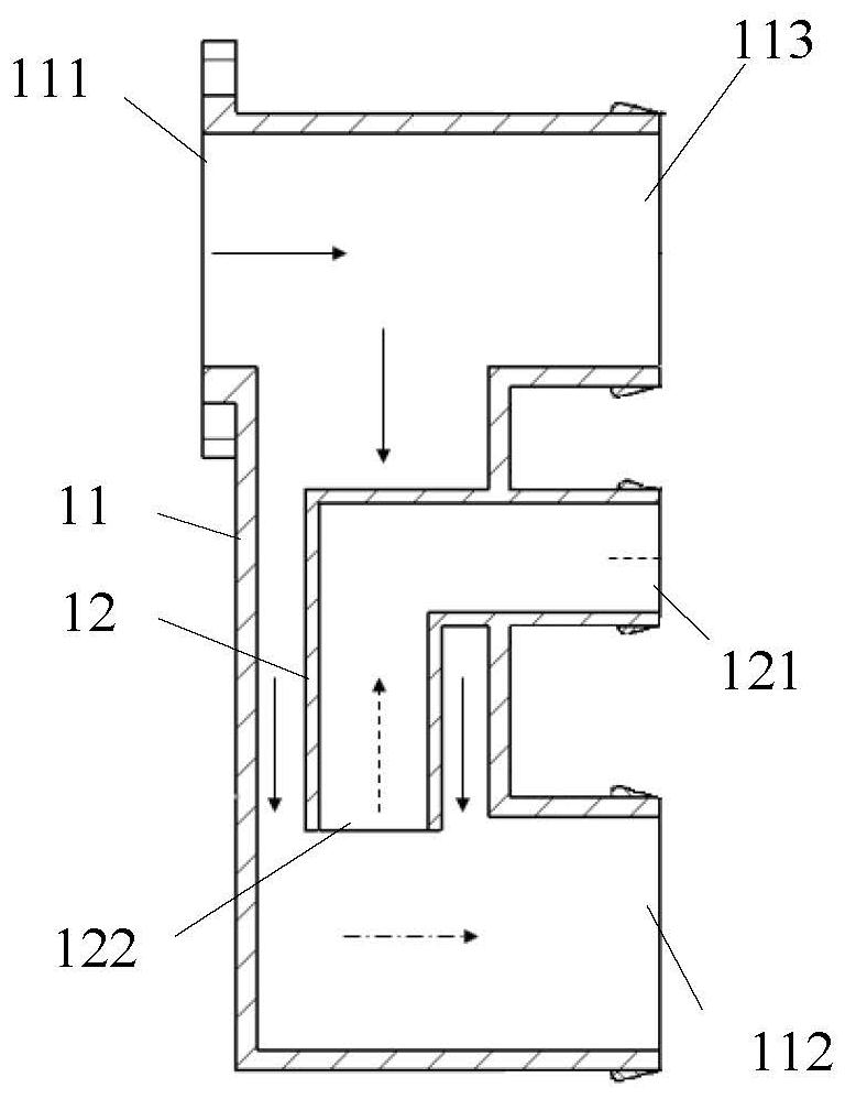
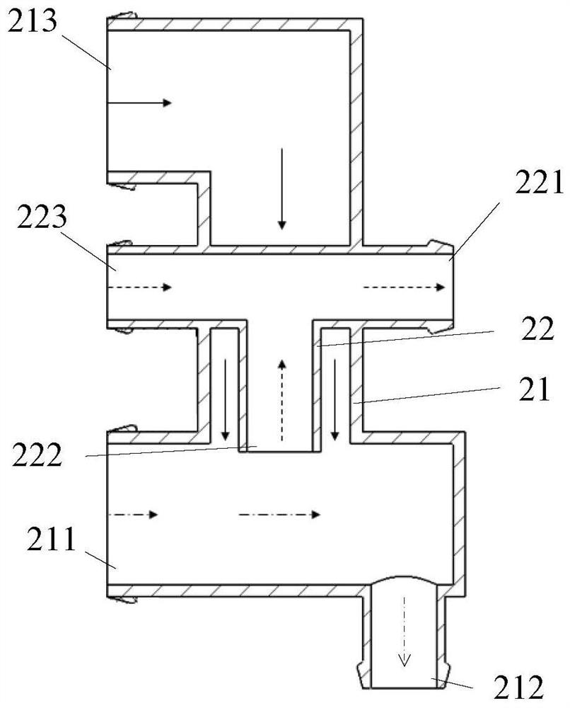
[0072] see Figure 1 to Figure 3 , figure 1 A cross-sectional view of the water separator provided for the first specific embodiment of the present invention; figure 2 A sectional view of the first water diversion section provided for the first specific embodiment of the present invention; image 3 A cross-sectional view of the water diversion section at the tail provided for the first specific embodiment of the present invention. Wherein, the dotted line arrows in the figure indicate the drainage direction of the separated gas, the solid line arrows indicate the flow direction of the mixed fluid, and the dotted line arrows indicate the flow direction of the separated liquid.
[0073] The water separator provided by the first specific embodiment of the present invention includes a first water diversion section 1 and a tail water diversion section 2, wherein:
[0074] The first part...
no. 2 Embodiment
[0094] The second specific embodiment of the present invention provides a water separator.
[0095] see Figure 4 to Figure 6 , Figure 4 A schematic diagram of the overall structure of the water separator provided for the second specific embodiment of the present invention; Figure 5 A cross-sectional view of the water separator provided for the second specific embodiment of the present invention; Image 6 A cross-sectional view of the middle water dividing section provided for the second specific embodiment of the present invention.
[0096] The only difference between the water separator provided by the second specific embodiment of the present invention and the water separator provided by the first specific embodiment of the present invention is that the water separator provided by the second specific embodiment of the present invention is different from that provided by the first specific embodiment. On the basis of the water separator, an intermediate water diversion ...
no. 3 Embodiment
[0109] The third specific embodiment of the present invention provides a water separator.
[0110] The difference between the water distributor provided by the third specific embodiment of the present invention and the water distributor provided by the second specific embodiment of the present invention is only that a plurality of intermediate water diversion sections are arranged in parallel in sequence, thus, the second specific embodiment provides On the basis of the water separator, the length of the pipeline is extended to realize more diversion and reverse drainage. For details, see Figure 5 and Image 6 , the water separator provided by the third specific embodiment of the present invention, in Figure 5 On the basis of this, multiple intermediate water diversion sections 3 are arranged in parallel.
[0111] Specifically, in the water separator provided by the third specific embodiment of the present invention:
[0112] The two adjacent middle water dividing sectio...
PUM
 Abstract
Description
Claims
Application Information
 - R&D
- Intellectual Property
- Life Sciences
- Materials
- Tech Scout
- Unparalleled Data Quality
- Higher Quality Content
- 60% Fewer Hallucinations
Browse by: Latest US Patents, China's latest patents, Technical Efficacy Thesaurus, Application Domain, Technology Topic, Popular Technical Reports.
© 2025 PatSnap. All rights reserved.Legal|Privacy policy|Modern Slavery Act Transparency Statement|Sitemap|About US| Contact US: help@patsnap.com


