Automatic lifting blending device

An automatic lifting and mixing technology, applied in the directions of shaking/oscillating/vibrating mixers, mixers, transportation and packaging, etc., can solve the problems of large defects, contaminated samples, surface damage of the cuvette, etc. simple structure

Inactive Publication Date: 2020-10-30
山东康华生物医疗科技股份有限公司
View PDF5 Cites 3 Cited by
  • Summary
  • Abstract
  • Description
  • Claims
  • Application Information

AI Technical Summary

Problems solved by technology

[0002] At present, there are mainly the following types of mixing: the first is stirring and mixing, but stirring and mixing requires the stirring mechanism to go deep into the cuvette, so this structure has very obvious defects such as cross-contamination and contaminated samples, so Large defects, limited conditions of use
The second is to rotate the structure, which is currently the most widely used in the field of chemiluminescence immunology, but t

Method used


Image

  • Automatic lifting blending device
  • Automatic lifting blending device
  • Automatic lifting blending device

Examples


Embodiment 1

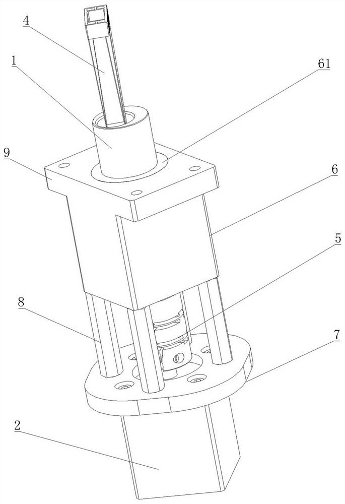
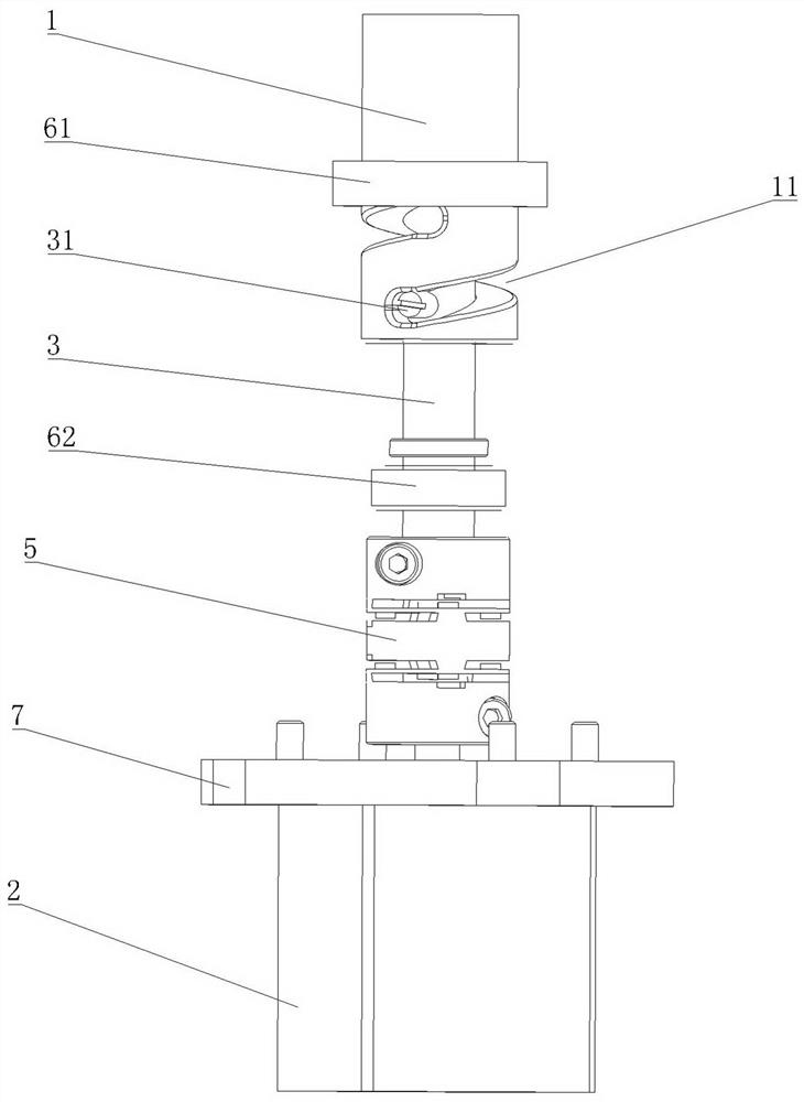
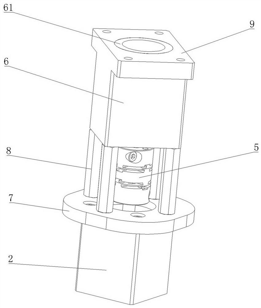
[0031] Embodiment 1: as attached Figure 1-8 As shown, an automatic lifting and mixing device includes a mixing head 1. The shape of the mixing head 1 is cylindrical. The mixing head 1 is connected with a positioning guide mechanism. Chute 11, the chute 11 is spirally arranged along the circumferential direction of the mixing head 1, the length of the chute 11 expanded is greater than the length of the outer circumference of the mixing head 1, the length of the chute 11 can be adjusted according to the needs, and the height of the chute 11 passes It is calculated that the vertical height of the chute 11 sliding along the pin shaft 31 is the rising or falling height of the mixing head 1, and the vertical height of the chute 11 is set as high as the vertical movement distance of the mixing head 1 is required. In the embodiment, due to the needs of the complete machine, the height set is 8mm, and the vertical height of the chute 11 is correspondingly set to 8mm. A pin 31 that can...

Embodiment 2

[0046] Embodiment 2: the chute 11 is a groove located on the inner wall of the first connection hole 12, the chute 11 is not in the form of a through groove, and the chute 11 is not connected with the outside world, so the pin shaft 31 can be pre-installed on the transmission shaft 3, the pin shaft 31 is connected to the transmission shaft 3 through elastic components, after the pin shaft 31 is compressed so that the pin shaft 31 is installed in the chute 11, the pin shaft 31 will return to its original position through the elastic component, and the transmission shaft 3 rotates, driving the pin shaft 31 rotation can also realize the lifting and mixing of the mixing head. It is also possible to process a round hole connected with the chute 11 on the mixing head 1. The pin shaft 31 can pass through the round hole, and the pin shaft 31 can be passed through the round hole. Threaded connection with the transmission shaft 3, after the pin shaft 31 is connected with the transmission...

Embodiment 3

[0048] Embodiment 3: The chute 11 is a groove located on the outer peripheral surface of the mixing head 1, the end of the transmission shaft 3 connected to the chute 11 is provided with a sleeve, the pin shaft 31 is arranged in the sleeve, and one end of the pin shaft 31 is Located in the chute 11, the other end of the pin shaft 31 can be fixedly connected to the sleeve. The pin shaft 31 can be connected to the sleeve through an elastic device, threaded, or welded. This form can also realize the pin The shaft 31 drives the lifting and rotation of the mixing head 1 .

[0049] All the other structures are the same as in Example 1.


PUM


Abstract

The invention provides an automatic lifting blending device which comprises a blending head and is characterized in that the blending head is connected with a positioning guide mechanism, the blendinghead is provided with a spirally-arranged sliding groove, a pin shaft capable of sliding relative to the sliding groove is arranged in the sliding groove, and the pin shaft is connected with a powerdriving device for driving the pin shaft to rotate in the circumferential direction of the blending head; the power driving device drives the pin shaft to rotate, and the sliding groove on the blending head slides along the pin shaft to realize the lifting and rotation of the blending head so that the lifting and rotation of the blending head can be realized by only one rotating transmission shaft, the structure is simple, the required space is small, the problem of stirring pollution cannot occur, the blending is stable, and the reaction cup cannot be damaged.

Description

technical field [0001] The invention relates to the field of fully automatic magnetic particle chemiluminescence immunoassay, in particular to an automatic lifting and mixing device. Background technique [0002] At present, there are mainly the following types of mixing: the first is stirring and mixing, but stirring and mixing requires the stirring mechanism to go deep into the cuvette, so this structure has very obvious defects such as cross-contamination and contaminated samples, so Large defects, limited conditions of use. The second is to rotate the structure, which is currently the most widely used in the field of chemiluminescence immunology, but the rotating structure needs to be adjusted to a certain height during installation, and the height difference determines the mixing effect, which depends on the installation deviation, so there are instability. There is another kind of shaking and mixing, which requires the structure to swing back and forth, which will ca...

Claims


Application Information

Patent Timeline
IPC IPC(8): B01F11/00
CPCB01F31/00B01F31/40B01F31/70B01F2101/23
Inventor 杨帆高海翟孙路璐王江勇高永峰李大伟
Owner 山东康华生物医疗科技股份有限公司
Why Eureka
Try Eureka