
Eureka
For R&D, Eureka makes reading and utilizing patents & technical documents easy.
Eureka AIR
Designed for self-driven R&D workflows. Generate viable solutions, solve complex R&D challenges, empower your innovation with AI.

Eureka Materials
Designed for material experts only. Revolutionize your material R&D, from search, analyze, to developing new materials.

TechResearch
Generate reliable direction feasibility study reports for your R&D in just a few steps.

TechSeek
Discover and master advanced knowledge NOW. Basics, ideas, possibilities, all at once.

TechMind
As an expert in R&D Theories, TechMind can generates customized viable solutions instantly.

TechRisk
Analyze your overall solution with one click, know your potential R&D risks in advance.

TechMonitor
Get weekly tech updates, stay abreast of the latest tech innovations and key insights.
Motor rotor clamp spring assembly machine
A technology for motor rotors and assembly machines, which is applied in metal processing, metal processing equipment, hand-held tools, etc., and can solve problems affecting the speed of motor assembly
- Summary
- Abstract
- Description
- Claims
- Application Information
AI Technical Summary
Problems solved by technology
Method used
Image

Examples
specific Embodiment approach 1
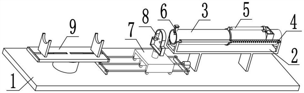
[0032] Combine below Figure 1-10Describe this embodiment. The present invention relates to the technical field of motor equipment, more specifically, a motor rotor circlip assembly machine, including an assembly and fixing support device 1, a tension spring storage and fixing device 2, a circlip storage cavity member 3, and a circlip top. Rely on the discharge member 4, telescopic connection device 5, circlip limit device 6, assembly translation member 7, circlip removal installation device 8 and rotor fixed storage device 9, put the motor rotor on the receiving transfer plate 9-1 and use two A support plate 9-3 fixes the device, allowing the translation slide seat 7-5 to slide to the right, allowing two jumper pins 8-4 to be inserted into the two holes of the jumper, and then allowing the limit clamping plate 6- 3. Move upwards, and at this moment the clip spring can be taken out. At this time, the limit clamp plate 6-3 will immediately descend and continue to limit the clip...
specific Embodiment approach 2
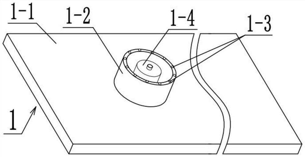
[0035] Combine below Figure 1-10 Describe this embodiment, this embodiment will further explain Embodiment 1. The described assembling and fixing support device 1 includes a fixed base plate 1-1, a support circular cavity 1-2, a receiving ball 1-3 and a motor I1-4, and the fixed base plate 1 -1 plays the role of bearing connection, the top of the left end of the fixed bottom plate 1-1 is fixedly connected with a supporting circular cavity 1-2, and the supporting circular cavity 1-2 can provide a connection space for multiple receiving balls 1-3, and the supporting circular cavity The top of 1-2 is uniformly rotated and connected with a plurality of receiving balls 1-3, and after being provided with a plurality of receiving balls 1-3, the receiving transfer plate 9-1 can be supported, which can increase the service life of the receiving transfer plate 9-1 , can also allow the rotating plate 9-1 to rotate smoothly, and the bottom of the fixed bottom plate 1-1 is fixedly connect...
specific Embodiment approach 3
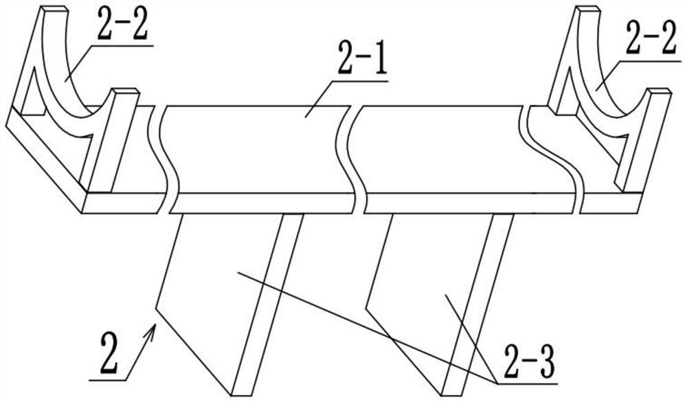
[0037] Combine below Figure 1-10 Describe this embodiment mode, this embodiment mode will further explain the second embodiment mode, the described tension spring storage and fixing device 2 includes a support waist plate 2-1, a fixed ear plate 2-2 and a leg riser 2-3, and the support waist plate 2 -1 plays the role of load-bearing connection, the left and right ends above the support waist plate 2-1 are fixedly connected with fixed lugs 2-2, and the two fixed lugs 2-2 can provide a fixed support for the circlip storage chamber 3-1. Space, the bottom of the supporting waist board 2-1 is fixedly connected with two outrigger vertical boards 2-3, and the two outrigger vertical boards 2-3 can provide a space for supporting and fixing the supporting waist board 2-1, and the two outrigger vertical boards 2-3 are fixedly connected above the fixed bottom plate 1-1.
PUM
 Abstract
Description
Claims
Application Information
 - R&D Engineer
- R&D Manager
- IP Professional
- Industry Leading Data Capabilities
- Powerful AI technology
- Patent DNA Extraction
Browse by: Latest US Patents, China's latest patents, Technical Efficacy Thesaurus, Application Domain, Technology Topic, Popular Technical Reports.
© 2024 PatSnap. All rights reserved.Legal|Privacy policy|Modern Slavery Act Transparency Statement|Sitemap|About US| Contact US: help@patsnap.com