

Stone moving machine
A mobile machine and mobile mechanism technology, applied in the field of mobile machines, can solve the problems of inconsistent stone standards and low efficiency, and achieve the effect of improving efficiency
- Summary
- Abstract
- Description
- Claims
- Application Information
AI Technical Summary
Problems solved by technology
Method used
Image

Examples
Embodiment 1
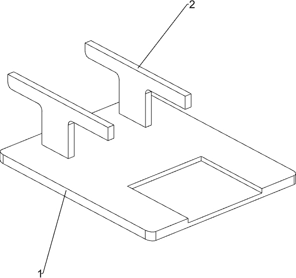
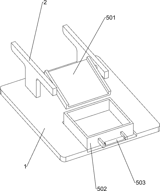
[0026] A stone moving machine such as Figure 1-3 As shown, it includes a bottom plate 1, a support frame 2, a moving mechanism 3 and a cutting mechanism 4. The top left side of the bottom plate 1 is fixedly connected with a support frame 2, and the top of the support frame 2 is provided with a moving mechanism 3. Between the outside of the right side of the support frame 2 A cutting mechanism 4 is connected.
[0027] When people need to cut the stone, first people place the stone body 7 on the moving mechanism 3, the moving mechanism 3 fixes the stone body 7, then start the moving mechanism 3 and the cutting mechanism 4, the moving mechanism 3 drives the stone body 7 to move to the cutting At the bottom of the mechanism 4, the cutting mechanism 4 moves downward. When the cutting mechanism 4 contacts the stone body 7, the cutting mechanism 4 quickly cuts the stone body 7. When people do not need to cut the stone, the moving mechanism 3 and the cutting mechanism 4 are closed. ...
Embodiment 2
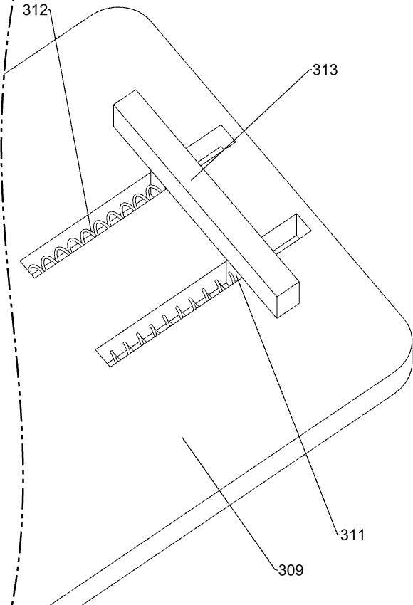
[0029] On the basis of Example 1, such as figure 1 and Figure 3-9 As shown, the moving mechanism 3 includes a mounting plate 301, a differential motor 302, a special-shaped block 303, a rotating rod 304, a dial 305, a first slide rail 306, a first slider 307, a fixed rod 308, a placement plate 309, a fixed Block 310, the second slide block 311, the first spring 312 and the rubber block 313, the first slide rail 306 is provided on the top of the front and rear sides of the support frame 2, and the first slide rail 306 is connected with the first slide rail 306 in a sliding manner. block 307, the first slide block 307 outside of the front side is evenly provided with fixed rod 308, and support frame 2 front side is provided with mounting plate 301, and differential motor 302 is installed on the top of mounting plate 301 front side, and on the output shaft of differential motor 302 Rotating rod 304 is provided, and special-shaped block 303 is arranged on the top of the rear sid...
PUM
 Abstract
Description
Claims
Application Information