Undercarriage aerodynamic load test device and design method thereof

A technology of aerodynamic load and test device, which is applied in the directions of ground installation, transportation and packaging, aircraft component testing, etc., can solve problems such as failure to meet the test requirements, and achieve the effects of convenient implementation, high reliability, and easy repeated disassembly and assembly.

Active Publication Date: 2020-10-30
LANDING GEAR ADVANCED MFG
View PDF12 Cites 4 Cited by
  • Summary
  • Abstract
  • Description
  • Claims
  • Application Information

AI Technical Summary

Problems solved by technology

Therefore, the conventional landing gear functional performance test cannot meet the test requirements

Method used


Image

  • Undercarriage aerodynamic load test device and design method thereof
  • Undercarriage aerodynamic load test device and design method thereof
  • Undercarriage aerodynamic load test device and design method thereof

Examples


Embodiment Construction

[0031] The present invention will be described in detail below with reference to the accompanying drawings and examples. It should be noted that, in the case of no conflict, the embodiments of the present invention and the features in the embodiments can be combined with each other. For the convenience of description, if the words "up", "down", "left" and "right" appear in the following, it only means that the directions of up, down, left and right are consistent with the drawings themselves, and do not limit the structure.

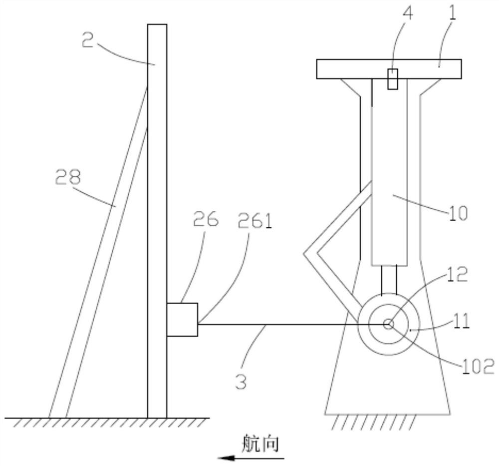
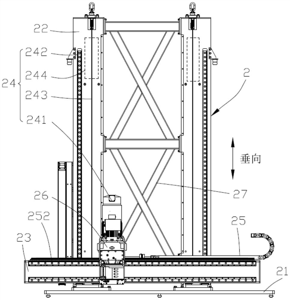
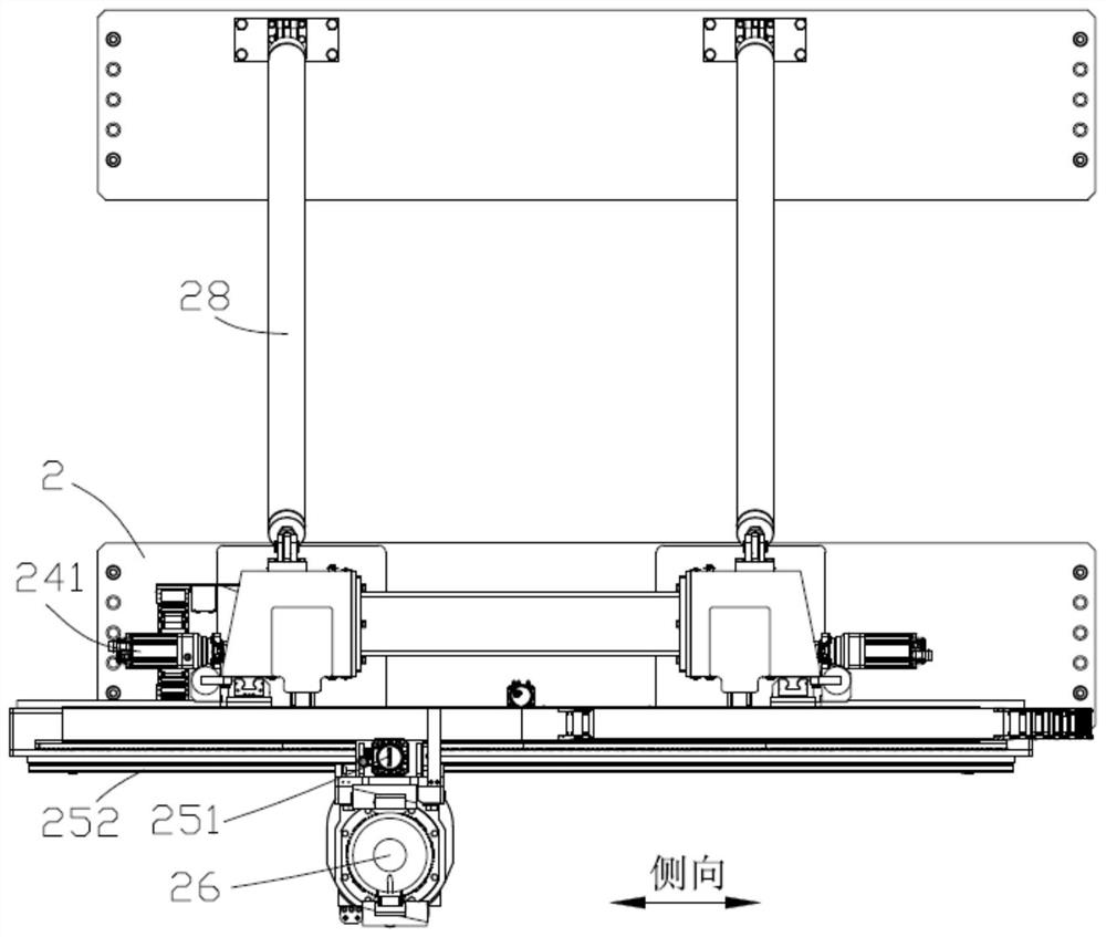
[0032] Such as Figure 1~3 As shown, a landing gear aerodynamic load test device provided in this embodiment includes a mounting frame 1 , a loading device 2 , a loading wire rope 3 , an angle sensor 4 and a mounting support 5 .

[0033] The mounting frame 1 is used to fix the landing gear 10 . The main shaft of the undercarriage 10 is fixed to the upper end of the mounting frame 1 by bolts. The dummy wheel assembly 11 is provided on the mounting frame...


PUM


Abstract

The invention provides an undercarriage aerodynamic load test device and a design method thereof. The undercarriage aerodynamic load test device comprises a mounting fixture and a loading device. An applying point is arranged on the loading device, and a loading point is arranged on the mounting fixture; in a static state, the loading point corresponds to positions of a central point of an undercarriage wheel shaft on lateral and vertical projection planes; and under the driving of the applying point, the loading point can move laterally, in a heading direction and in a vertical direction, anda displacement track of the loading point is matched with the displacement track of the undercarriage. Compared with the prior art, the undercarriage aerodynamic load test device provided by the invention has advantages that the retraction and extension of the undercarriage under the influence of an aerodynamic load are truly simulated; and the structure is novel, reliability is high, and repeated dismounting is convenient.

Description

technical field [0001] The invention relates to a landing gear aerodynamic load test device and a design method thereof. Background technique [0002] Landing gear is an accessory device used to support the aircraft and move on the ground when the lower part of the aircraft is used for takeoff and landing or ground taxiing. The landing gear includes a main shaft and a wheel arranged at one end of the main shaft. The main shaft connects the wheels to the aircraft and transfers impact loads during landing and taxiing to the aircraft. Therefore, the landing gear is the only component that supports the entire aircraft and is an integral part of the aircraft. [0003] In the design of landing gear, the landing gear retraction test is a common functional performance test, which is mainly used to verify whether the retractable functional performance of the product meets the design requirements, and can set a single point of failure to verify the reliability of the retractable sys...

Claims


Application Information

Patent Timeline
Patent Type & Authority Applications(China)
IPC IPC(8): B64F5/60B64F5/00
CPCB64F5/60B64F5/00
Inventor 侯博之路红伟孙继勇王小锋汪赵宏王慧锋
Owner LANDING GEAR ADVANCED MFG
Why Eureka
Try Eureka