Iron nail box loading machine

A cartoning machine and iron nail technology, which is applied in the direction of packaging, transportation and packaging, single objects, etc., can solve the problems of iron nails easy to fall from the hand, low work efficiency, laborious and other problems

Active Publication Date: 2020-10-30
SHANXI YUCI BROAD WIRE PRODS
View PDF6 Cites 0 Cited by
  • Summary
  • Abstract
  • Description
  • Claims
  • Application Information

AI Technical Summary

Problems solved by technology

[0005] In order to overcome the large number of iron nails, the human hand needs to move back and forth continuously, which is laborious and low in work efficiency, and some iron nails are easy to fall from the hand during the process of moving the iron nails to the box. Technical problem: To provide a nail cartoning machine that can replace manual nails into the box, which saves labor and has high work efficiency, and the nails are not easy to fall off.

Method used


Image

  • Iron nail box loading machine
  • Iron nail box loading machine
  • Iron nail box loading machine

Examples


Embodiment 1

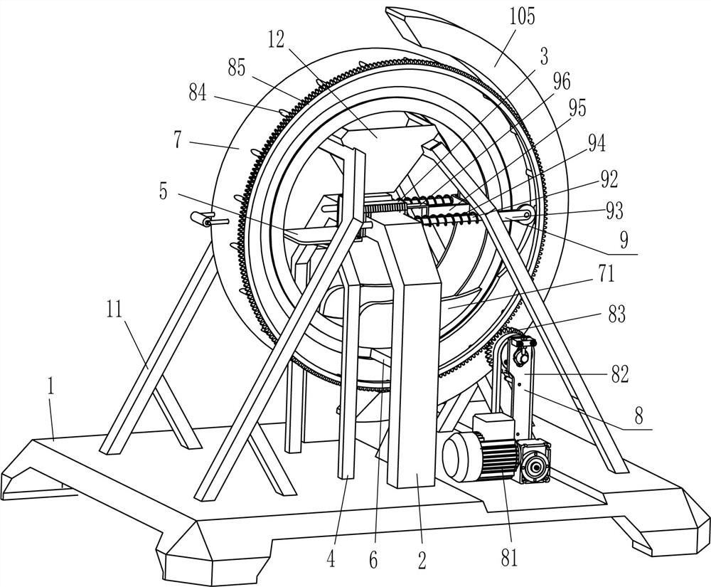
[0023] A nail cartoning machine, such as figure 1 As shown, it includes a base 1, an L-shaped plate 2, an electromagnet 3, a supporting plate 4, a placement plate 5, a guide block 6, a ring frame 7, a driving plate 71, a driving mechanism 8 and a pushing mechanism 9, and the top middle of the base 1 L-shaped plates 2 are fixedly connected to the front and rear sides, electromagnets 3 are fixedly connected to the inner ends of the L-shaped plates 2 on the front and rear sides, and the electromagnets 3 on the front and rear sides are matched with each other. 4. A placement plate 5 is fixed between the inner ends of the front and rear support plates 4 to allow the box to be placed. The placement plate 5 is located on the left side of the electromagnet 3 on the front and rear sides. The material mechanism 9, the front and rear sides of the L-shaped plate 2 are fixedly connected to the lower part of the inner side of the guide block 6, and the ring frame 7 is slidably provided betwee...

Embodiment 2

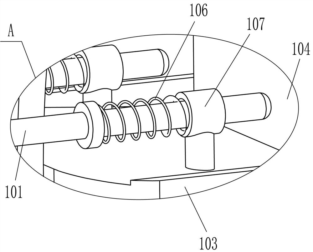
[0030] On the basis of Example 1, such as Figure 1-Figure 3 As shown, the conveying mechanism 10 is also included. The conveying mechanism 10 includes a sliding rod 101, a contact wheel 102, a baffle 103, a swing plate 104, an arc block 105, a second spring 106, and a guide sleeve 107. The left side of the ring frame 7 The middle part is symmetrically slidable through the sliding rod 101. The left ends of the front and rear sliding rods 101 are rotatably connected with a contact wheel 102. The right part of the sliding rod 101 is slidingly covered with a guide sleeve 107, and the left side of the guide sleeve 107 A second spring 106 is wound around the right part of the sliding rod 101. A baffle 103 is fixedly connected to the left part of the ring frame 7. The top of the baffle 103 is fixedly connected to the bottom of the front and rear guide sleeves 107, and the right end of the baffle 103 is hinged. There is a swing plate 104, an arc block 105 is installed in the middle of...

Embodiment 3

[0033] On the basis of Example 1 and Example 2, such as figure 1 , figure 2 with Figure 4 As shown, it also includes a support frame 11 and a lower hopper 12. The bottom left and right sides of the top of the base 1 are symmetrically fixed to the front and rear with the support frame 11, and the bottom hopper 12 is fixed between the tops of the four support frames 11. The electromagnets 3 on both sides are directly above.

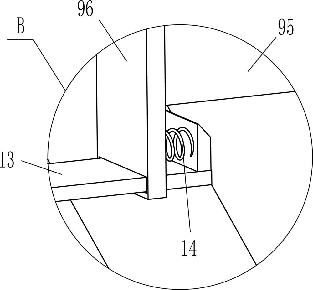
[0034] It also includes an L-shaped baffle plate 13 and a third spring 14. The lower part of the L-shaped push plate 96 is slidably connected with an L-shaped baffle plate 13, and the inner right side of the L-shaped baffle plate 13 and the L-shaped push plate 96 A third spring 14 is symmetrically connected between the lower parts of the outer right side surface.

[0035] When the swinging plate 104 swings inward without blocking the iron nails, the iron nails fall down into the lower hopper 12, and the iron nails in the lower hopper 12 fall between the electr...


PUM


Abstract

The invention relates to a box loading machine, in particular to an iron nail box loading machine. According to the iron nail box loading machine, iron nails can be loaded into boxes by replacing manual work, labor is saved, the working efficiency is high, and the iron nails are not prone to falling off. The iron nail box loading machine comprises a base and two electromagnets, wherein L-shaped plates are symmetrically and fixedly connected to the middle of one side of the base; and the electromagnets are fixedly connected to the end parts, away from the base, of the L-shaped plates, and the two electromagnets are mutually matched. According to the iron nail box loading machine, a proper amount of iron nails are thrown between the electromagnets on the front and rear sides to be sucked into a horizontal state, then a reducing motor is started to rotate forward, so that an annular frame can rotate reversely to drive a driving plate to rotate reversely, the driving plate rotates reversely to be in contact with a U-shaped plate, an L-shaped pushing plate moves to the left to push the iron nails between the electromagnets into the boxes, it is not necessary to put the iron nails into the boxes by hands, the labor is saved, and the working efficiency is high.

Description

Technical field [0001] The invention relates to a cartoning machine, in particular to a nail cartoning machine. Background technique [0002] Iron nails have a flat head at one end and a sharp end at the other end. They are mainly used for fixing or connecting. When iron nails are produced, due to the large amount, they will be put into the box for collection in order to facilitate transportation. Packing more nails will make the nails neatly placed in the box. [0003] At present, most people cooperate with the machine to put the iron nails neatly into the box. First, you need to start the machine to suck the right amount of iron nails, and make the iron nails level, then the person will hold the nails by hand. Take it down and put it in the box. Due to the large number of iron nails, the human hand needs to move back and forth continuously. Over time, it is more laborious, and the work efficiency is low. In the process of moving the nails to the box, some nails are easy to move ...

Claims


Application Information

Patent Timeline
Patent Type & Authority Applications(China)
IPC IPC(8): B65B35/18B65B5/10
CPCB65B35/18B65B5/106B65B5/105
Inventor 张金良
Owner SHANXI YUCI BROAD WIRE PRODS
Why Eureka
Try Eureka