
Water gushing plugging device and control method thereof

A technology of a plugging device and a control method, which is applied in the directions of earthwork drilling, bolt installation, sealing/isolation, etc., can solve problems such as inability to efficiently and conveniently block water gushing, and achieve avoidance of adverse effects, sufficient and reliable water gushing plugging, The effect of reliable plugging

Active Publication Date: 2020-10-30
CHINA RAILWAY ENGINEERING EQUIPMENT GROUP CO LTD
View PDF12 Cites 0 Cited by
  • Summary
  • Abstract
  • Description
  • Claims
  • Application Information

AI Technical Summary

Problems solved by technology

[0005] In view of the deficiencies in the above-mentioned background technology, the present invention proposes a water gushing sealing device and its control method, which solves the technical problem that the water gushing cannot be blocked efficiently and conveniently during tunnel excavation

Method used


Image

  • Water gushing plugging device and control method thereof
  • Water gushing plugging device and control method thereof
  • Water gushing plugging device and control method thereof

Examples


Embodiment 1

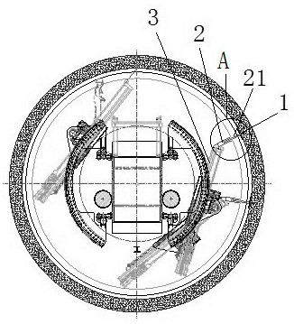
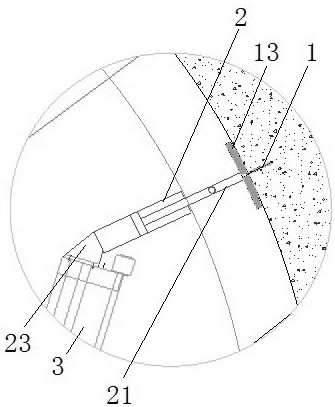
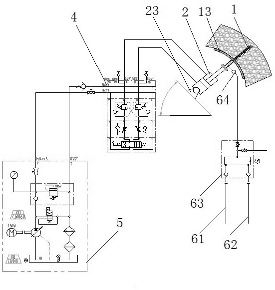
[0028] Embodiment 1, a kind of gushing water blocking device, such as image 3 , 4 As shown, it includes a water stop rod 1 made of seamless steel pipe, and uses the water stop rod 1 to block the water gushing hole. Such as figure 1 , 2 As shown, the water stop rod 1 is connected with an oil cylinder 2, and the oil cylinder 2 is connected with the rotating part of the rock bolter 3, and the oil cylinder 2 is connected with the hydraulic pump station 5 through the control valve group 4. The rotation of the bolter 3 can drive the oil cylinder 2 to rotate in the tunnel, and can drive the oil cylinder 2 to any position that needs to be blocked for construction. The extension of the oil cylinder 2 can drive the water stop rod 1 to insert into the water gushing hole to realize the water gushing hole automatic blocking.

[0029] Further, the oil cylinder 2 is hinged on the rotating part of the rock bolt 3 through the hinge seat 23, the hinge seat 23 is a universal ball joint seat...

Embodiment 2

[0034] Embodiment 2, a control method of a water gushing sealing device, comprising the following steps:

[0035] ① Control the rotation of the bolter 3 until the water stop rod 1 reaches the water gushing hole;

[0036] ② Control the extension of the oil cylinder 2 until the oil cylinder 2 drives the water stop rod 1 to insert into the water gushing hole to ensure that the arc-shaped sealing plate 13 fits with the wall surface at the front end of the water gushing hole;

[0037] ③ If the water gushing is effectively controlled, use expansion bolts to fix the arc-shaped sealing plate 13 on the wall;

[0038] ④ If the water gushing is not under control, control the high-pressure grouting system to perform double-liquid grouting into the water stop rod 1, and use expansion bolts to fix the arc-shaped sealing plate 13 on the wall;

[0039] ⑤Remove the connection between the water stop rod 1 and the oil cylinder 2, and remove the oil cylinder 2 from the rock bolter 3.


PUM


Abstract

The invention discloses a water gushing plugging device and a control method thereof, and solves the technical problem that gushing water cannot be plugged efficiently and conveniently during tunnel excavation. The water gushing plugging device comprises a water stop rod, wherein the water stop rod is utilized for plugging a water gushing hole; the water stop rod is connected with an oil cylinder,and the oil cylinder is connected onto a rotating part of a roof bolter and is connected with a hydraulic pump station through a control valve group; and the roof bolter rotates to drive the oil cylinder to rotate in a tunnel, the oil cylinder can be driven to any position needing plugging construction, the water stop rod can be driven by extending of the oil cylinder to be inserted into the water gushing hole, and therefore, automatic plugging for the water gushing hole is realized. The plugging structure can not only perform reliable plugging on the water gushing holes with different sizes,but also can be controlled automatically, so that a series of adverse effects caused by artificial operation are avoided.

Description

technical field [0001] The invention belongs to the technical field of water gushing control, in particular to a water gushing blocking device and a control method thereof. Background technique [0002] With the rapid development of domestic mountain tunnels, more and more TBMs are used for tunnel construction, and it has quickly become the development trend of mountain tunnel construction. During the construction process, when there is a sudden water gushing in a tunnel with developed groundwater, it will not only cause a large amount of groundwater loss and damage to the environment, but also the tunnel will be flooded and cannot continue to be excavated, causing extremely serious adverse effects on the tunnel construction. [0003] After retrieval, the existing patent application for invention with the application date of 2018.04.02 and the application number of 201810281946.8 discloses a tunnel drilling water gushing blocking device and method. The tunnel drilling water ...

Claims


Application Information

Patent Timeline
Patent Type & Authority Applications(China)
IPC IPC(8): E21B33/12E21B33/13E21D20/00
CPCE21B33/1208E21B33/13E21D20/003
Inventor 朱雷郭付军高可可杜旭峰李嘉欣郭志勇李孝瑾周小磊朱团辉郑博徐志良马志勇蔡留金冯超强
Owner CHINA RAILWAY ENGINEERING EQUIPMENT GROUP CO LTD
Learn More