
Associated gas recovery and treatment device and method

A technology for recovery and treatment of associated gas, which is used in earth-moving drilling, gas fuel, wellbore/well components, etc. It can solve the problems of insufficient production of associated gas to meet the economic requirements of pipeline gathering and transportation, waste of energy resources, etc. The effect of low utilization rate of pipeline, saving construction cost and reasonable collection and utilization

Active Publication Date: 2020-10-30
QINGDAO UNIV OF SCI & TECH
View PDF7 Cites 1 Cited by
  • Summary
  • Abstract
  • Description
  • Claims
  • Application Information

AI Technical Summary

Problems solved by technology

However, because oil wells are often located in remote areas, and the associated gas production of a single oil well is not enough to meet the economic requirements of pipeline gathering and transportation, many oil wells choose to directly ignite associated gas for emptying, which not only causes a waste of energy resources, also produces large amounts of greenhouse gases

Method used


Image

  • Associated gas recovery and treatment device and method

Examples


Embodiment 1

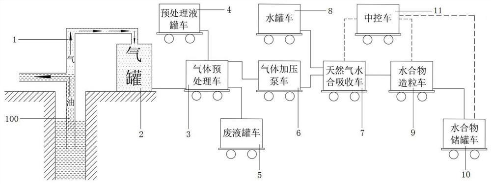
[0012] The main structure of the associated gas recovery and processing device and method involved in this embodiment includes a gas collection pipeline 1, a gas tank 2, a gas pretreatment vehicle 3, a pretreatment liquid tank vehicle 4, a waste liquid tank vehicle 5, a gas pressurization pump vehicle 6, a natural gas Hydration absorption vehicle 7, water tank vehicle 8, hydrate granulation vehicle 9, hydrate storage tank vehicle 10 and central control vehicle 11; one end of the gas collection pipeline 1 is connected to the oil pipeline 100, and the other end of the gas collection pipeline 1 is connected to the gas tank 2 connection, the gas tank 2 is connected to the gas pretreatment truck 3 in pipeline, the gas pretreatment truck 3 is connected to the pretreatment liquid tank truck 4, the waste liquid tank truck 5 and the gas pressurized pump truck 6 respectively, and the gas pressurized pump truck 6 Pipeline connection with natural gas hydration absorption vehicle 7, natural...

Embodiment 2

[0016] The process of the associated gas recovery and treatment method involved in this embodiment includes six steps of collection, pretreatment, pressurization, hydration, granulation and collection:

[0017] Collection: through the gas collection pipeline 1, the oil well associated gas is collected to the gas tank 2 for storage;

[0018] Pretreatment: After the associated gas enters the gas pretreatment vehicle 3 from the gas tank 2, the large particle impurities and crude oil impurities in the associated gas are removed by mechanical methods, and the associated gas is desulfurized and decarbonized by the pretreatment liquid absorption method, and separated by membrane Technology to separate natural gas from associated gas, pretreatment liquid waste liquid, large particle impurities and crude oil impurities are discharged into the waste liquid tanker 5, natural gas is discharged into the gas pressurized pump truck 6, and the pretreatment liquid is provided by the pretreatmen...


PUM

PropertyMeasurementUnit
compressive strengthaaaaaaaaaa

Abstract

The invention belongs to the technical field of associated gas recovery and treatment, and relates to an associated gas recovery and treatment device and method. A main structure of the device comprises a gas collection pipeline, a gas tank, a gas pretreatment vehicle, a pretreatment tank truck, a waste liquid tank truck, a gas booster pump truck, a natural gas hydration absorption vehicle, a water tank truck, a hydrate granulation vehicle, a hydrate storage tank truck and a central control vehicle, the technological process of the method comprises six steps of collection, pretreatment, pressurization, hydration, granulation and collection, and on the basis of the advantages of safe storage and transportation and mild conditions of hydrate in natural gas storage and transportation, oil well associated gas is recovered and treated; and the device is simple in structure and convenient to disassemble and assemble, a large amount of pipeline laying work can be avoided through a movable framework, the construction cost is saved, the defects that the pipeline is low in utilization rate and even abandoned are overcome, the oil well associated gas can be conveniently and rapidly convertedinto hydrate type energy to be stored and transported, and the realization of energy conservation, emission reduction and environmental protection is facilitated.

Description

Technical field: [0001] The invention belongs to the technical field of associated gas recovery and treatment, and in particular relates to an associated gas recovery and treatment device and method, which can conveniently and quickly convert oil well associated gas into energy in the form of hydrates for storage and transportation. Background technique: [0002] The rapid development of society means that more energy is needed to provide the driving force for development. Economic development is often accompanied by serious pollution, which is contrary to the development concept of environmental protection. In order to balance economic development and environmental protection at the same time, it is necessary to seek more high-quality and clean energy. Due to its full combustion and environmental friendliness, the proportion of natural gas in the energy consumption structure is increasing year by year. However, with the development of the national economy, energy consumpti...

Claims


Application Information

Patent Timeline
Patent Type & Authority Applications(China)
IPC IPC(8): E21B43/00E21B43/34E21B21/07E21B41/00C10L3/10
CPCE21B43/006E21B43/34E21B21/07C10L3/108E21B41/00
Inventor 王飞张国栋
Owner QINGDAO UNIV OF SCI & TECH
Learn More