Compact three-dimensional motion mechanism

A technology of three-dimensional motion and motion mechanism, which is applied to electromechanical devices, mechanical equipment, electric components, etc., and can solve the problems of large space occupation, large volume and weight, and large mechanism height.

Active Publication Date: 2020-10-30
CHANGCHUN INST OF OPTICS FINE MECHANICS & PHYSICS CHINESE ACAD OF SCI
View PDF11 Cites 0 Cited by
  • Summary
  • Abstract
  • Description
  • Claims
  • Application Information

AI Technical Summary

Problems solved by technology

Although the structure of the three-dimensional motion mechanism in the prior art can conveniently realize the three-dimensional motion driving of the load, the overall structure of the three-dimensional motion mechanism is in a vertically stacked shape. Occupies a lot, and there are many connecting parts between the two motion mechanisms, resulting in a large volume and weight

Method used


Image

  • Compact three-dimensional motion mechanism
  • Compact three-dimensional motion mechanism
  • Compact three-dimensional motion mechanism

Examples


Embodiment Construction

[0026] The following will clearly and completely describe the technical solutions in the embodiments of the present invention with reference to the accompanying drawings in the embodiments of the present invention. Obviously, the described embodiments are only some, not all, embodiments of the present invention. Based on the embodiments of the present invention, all other embodiments obtained by persons of ordinary skill in the art without making creative efforts belong to the protection scope of the present invention.

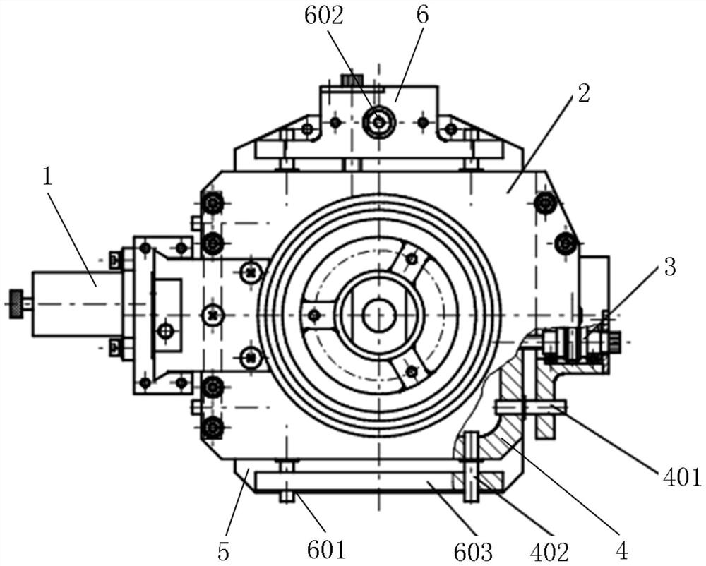
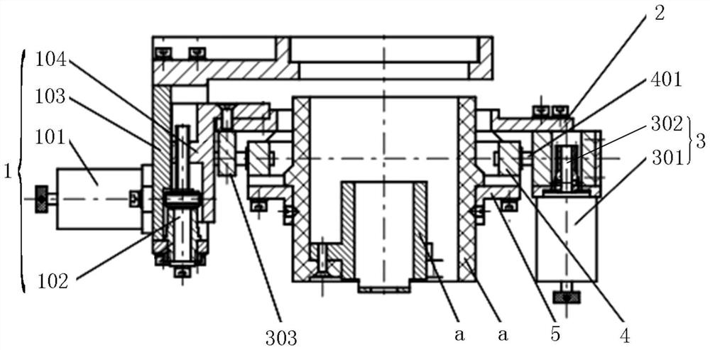
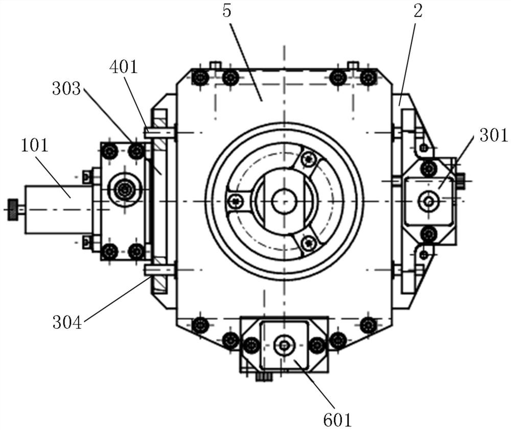
[0027] Please refer to figure 1 , figure 2 , image 3 , figure 1 It is a schematic diagram of the overall structure of a specific embodiment provided by the present invention, figure 2 for figure 1 front half-section view of image 3 for figure 1 bottom view.

[0028] In a specific embodiment provided by the present invention, the compact three-dimensional motion mechanism mainly includes a Z-axis motion mechanism 1, a connecting fixed plate 2, an X-a...


PUM


Abstract

The invention discloses a compact three-dimensional motion mechanism. The compact three-dimensional motion mechanism comprises a Z-axis motion mechanism, a connecting fixed plate, an X-axis motion mechanism, a horizontal moving plate, a synchronous follower plate and a Y-axis motion mechanism, wherein the connecting fixed plate is connected with the output end of the Z-axis motion mechanism, the X-axis motion mechanism is arranged on the connecting fixed plate, the horizontal moving plate is connected with the output end of the X-axis motion mechanism, the synchronous follower plate can be connected with the bottom surface of the horizontal moving plate in a Y-direction movement manner, the Y-axis motion mechanism is arranged on the surface of the synchronous follower plate, the output endof the Y-axis motion mechanism is connected with the horizontal moving plate, and the surface of the synchronous follower plate is used for installing loads. Therefore, the Z-axis motion mechanism isused for driving the connecting fixed plate, the X-axis motion mechanism is used for driving the horizontal moving plate, the Y-axis motion mechanism is used for driving the synchronous follower plate, three-dimensional space motion of the loads can be realized smoothly, and meanwhile a non-laminated installation structure (a horizontal distribution structure) is formed. Therefore, compared witha laminated installation structure in the prior art, the overall height of the compact three-dimensional motion mechanism can be significantly reduced, and space occupation is reduced.

Description

technical field [0001] The invention relates to the technical field of motion mechanisms, in particular to a compact three-dimensional motion mechanism. Background technique [0002] A three-dimensional motion mechanism is a commonly used motion mechanism or drive mechanism, which can drive a load or a workpiece to perform three-dimensional motion in space. Generally, a three-dimensional motion mechanism mainly includes three-axis motion degrees of freedom of X-Y-Z, that is, two-direction plane motion in the horizontal plane and vertical lifting motion. [0003] At present, three-dimensional motion mechanisms are often assembled by stacking three single-axis motion mechanisms, such as installing a Z-axis motion mechanism at the bottom, stacking an X-axis motion mechanism in the middle, and stacking a Y-axis motion mechanism at the top. Although the structure of the three-dimensional motion mechanism in the prior art can conveniently realize the three-dimensional motion driv...

Claims


Application Information

Patent Timeline
IPC IPC(8): F16H37/12H02K7/10
CPCF16H37/124H02K7/10
Inventor 吕涛付东辉陈小云阚卓娜
Owner CHANGCHUN INST OF OPTICS FINE MECHANICS & PHYSICS CHINESE ACAD OF SCI
Why Eureka
Try Eureka