Flange convenient to detach and install

A technology of flanges and flange pieces, which is applied in the field of flanges that are easy to disassemble and assemble, and can solve problems such as time-consuming and labor-intensive

Inactive Publication Date: 2020-10-30
浙江至丰法兰科技有限公司
View PDF6 Cites 4 Cited by
  • Summary
  • Abstract
  • Description
  • Claims
  • Application Information

AI Technical Summary

Problems solved by technology

[0002] Flanges are used for interconnection between pipelines and are the most commonly used connecting parts on pipelines. Traditional flanges have bolt holes, and then bolts are used to fix the flanges. Flange connections are very convenient to use and can withstand Larger pressure, flange connection is widely used in industrial pipelines, but in the process of installing or disassembling ordinary flanges, bolts need to be installed or disassembled one by one, which is time-consuming and laborious

Method used


Image

  • Flange convenient to detach and install
  • Flange convenient to detach and install
  • Flange convenient to detach and install

Examples


Embodiment 1

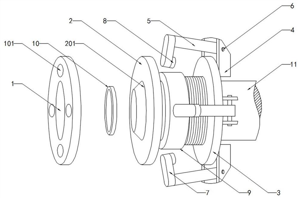
[0027] see Figure 1-3 , including a first flange piece 1, a second flange piece 2 and a pipe 11 fixedly connected to the second flange piece 2, a cylindrical groove 101 is provided on the side wall of the first flange piece 1 away from the second flange piece 2 , a positioning pin 8 is inserted into the cylindrical groove 101 and the length of the positioning pin 8 is less than the depth of the cylindrical groove 101, the pipe 11 is provided with a fixed ring 3, and the fixed ring 3 is fixedly connected to the side away from the second flange 2 The hinge seat 4 is hinged with a pull rod 5 through a rotating shaft 6, the rotating shaft 6 on the hinge seat 4 is located outside the fixed ring 3, the end of the pull rod 5 is fixedly connected with a connecting piece 7, and on the side where the connecting piece 7 is connected with the pull rod 5 Fixedly connected with a positioning pin 8, when the positioning pin 8 is inserted into the inside of the cylindrical groove 101, the pu...

Embodiment 2

[0029] see Figure 1-3 , the second flange piece 2 has a tapered ring 201 on the side wall close to the first flange piece 1, and the first flange piece 1 has a circular groove 102 on the side wall close to the second flange piece 2, and the tapered ring 201 is inserted into the inside of the ring groove 102, the ring groove 102 has a backing ring 10, the tapered ring 201 abuts against the side wall of the backing ring 10, and the first flange piece 1 and the second flange piece 2 are press fit , so that the connection of the pipeline 11 has better sealing performance.

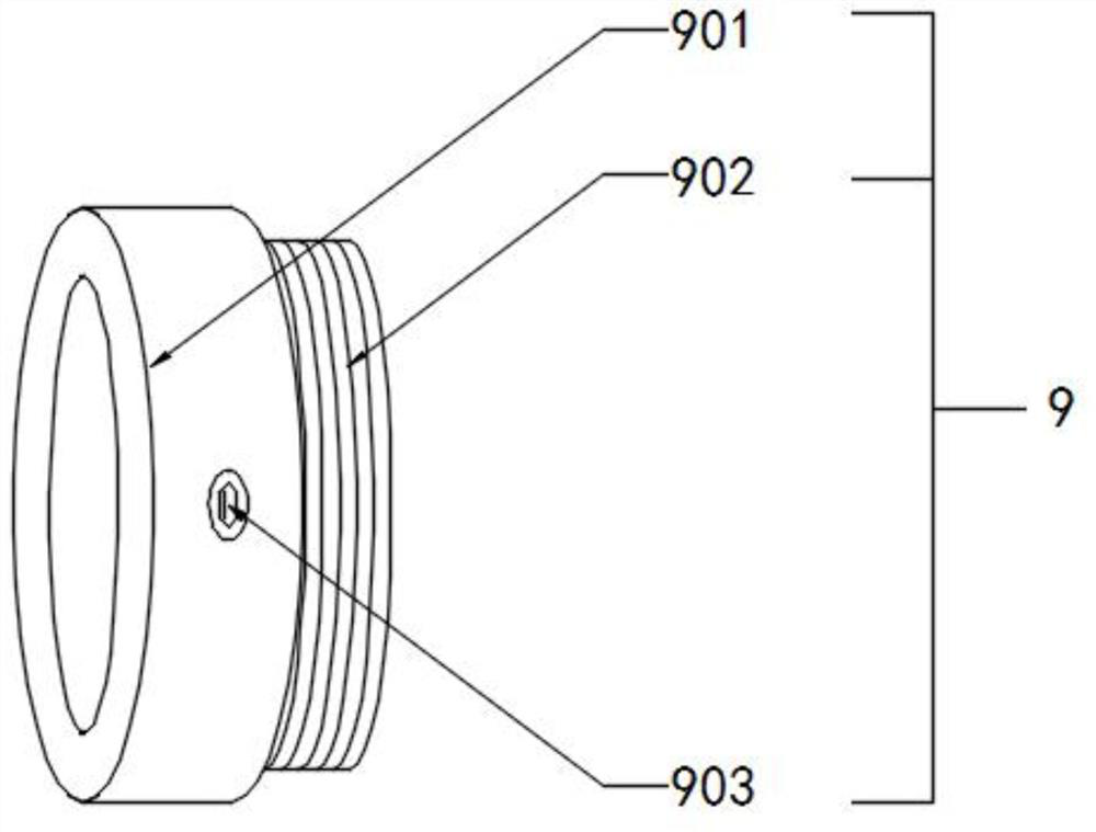
[0030] Working principle: the known flange is a connecting member for the end of the pipeline 11. The fixed connection between the first flange piece 1 and the second flange piece 2 makes the pipeline 11 sealed. When in use, the fixed ring 3 and the pressurized The mechanism 9 is sleeved on the pipeline 11. After the threaded cylinder 902 and the fixing ring 3 are fixed by spot welding, the sleeve 901 is adju...


PUM


Abstract

The invention discloses a flange convenient to detach and install. The flange comprises a first flange sheet, a second flange sheet and a pipeline fixedly connected with the second flange sheet. Cylinder grooves are formed in the side wall, away from the second flange sheet, of the first flange sheet. A fixed ring is arranged on the pipeline in a sleeving manner. Hinged supports are fixedly connected to the side face, away from the second flange sheet, of the fixed ring. A pull rod is hinged to each hinged support through a rotating shaft. The end portion of each pull rod is fixedly connectedwith a connection piece. A positioning pin is fixedly connected to the side face, connected with the corresponding pull rod, of each connection piece. A pressurization mechanism arranged on the pipeline in a sleeving manner is arranged between the fixed ring and the second flange sheet. The pressurization mechanism is mainly composed of a sleeve, a threaded barrel and an insertion hole. In the flange, by means of the pull rods hinged to the fixed ring, the positioning pins can be inserted in the cylinder grooves in the first flange sheet through the connection pieces, the sleeve in the pressurization mechanism is screwed, the first flange sheet is tightly pulled through the pull rods, flange connection positioning can be precise, the installation and detachment time is saved, and efficiency is high.

Description

technical field [0001] The invention relates to the technical field of flanges, in particular to a flange that is easy to assemble and disassemble. Background technique [0002] Flanges are used for interconnection between pipelines and are the most commonly used connecting parts on pipelines. Traditional flanges have bolt holes, and then bolts are used to fix the flanges. Flange connections are very convenient to use and can withstand Higher pressure, flange connection is widely used in industrial pipelines, but in the process of ordinary flange installation or disassembly, bolts need to be installed or disassembled one by one, which is time-consuming and laborious. [0003] Therefore, the present invention provides a flange that is easy to assemble and disassemble. Contents of the invention [0004] The object of the present invention is to provide a flange that is easy to assemble and disassemble in order to solve the above problems. [0005] In order to achieve the a...

Claims


Application Information

Patent Timeline
Patent Type & Authority Applications(China)
IPC IPC(8): F16L23/024F16L23/18
CPCF16L23/024F16L23/18
Inventor 章蓉王胜峰
Owner 浙江至丰法兰科技有限公司
Why Eureka
Try Eureka