Digital media suspension device

A suspension device, digital media technology, applied in the direction of machine/stand, supporting machine, mechanical equipment, etc., can solve the problems of unstable state and position deviation of digital media

Active Publication Date: 2020-10-30
XUCHANG UNIV
View PDF8 Cites 0 Cited by
  • Summary
  • Abstract
  • Description
  • Claims
  • Application Information

AI Technical Summary

Problems solved by technology

[0003] When the existing digital media is suspended, it is generally hung on the ring by a single hook. This kind of suspension method is likely to cause the suspended digital

Method used


Image

  • Digital media suspension device
  • Digital media suspension device
  • Digital media suspension device

Examples


Embodiment 1

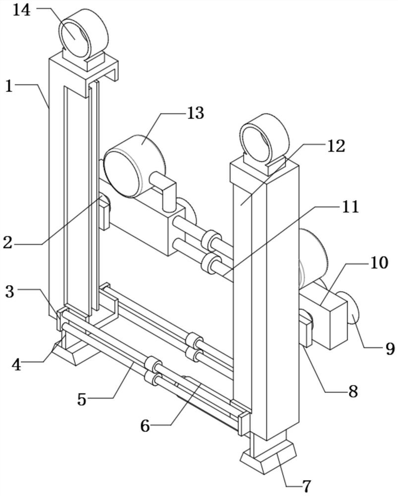
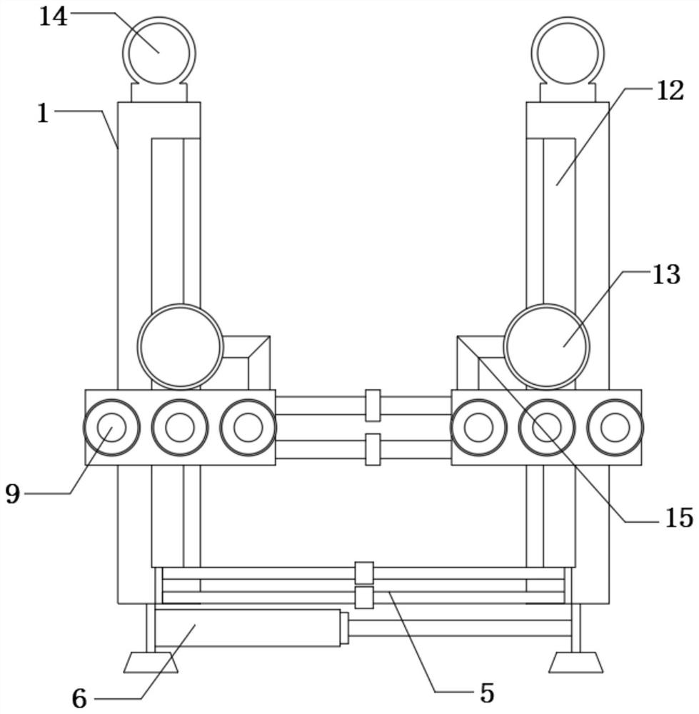
[0027] refer to Figure 1-4 , a digital media suspension device, comprising two limit frames 1 and chute 23, the outer walls of the same side of the two limit frames 1 are fixedly connected with connecting plates 8, and the outer walls of the two connecting plates 8 are fixedly connected with Hydraulic cylinder 2, the two hydraulic cylinders 2 are connected with a synchronous hydraulic system, the other ends of the two hydraulic cylinders 2 are fixedly connected with an air plate 10, and the outer walls of one side of the two air plates 10 are provided with split holes 21 at equal distances, each The outer walls of each split hole 21 are fixedly connected with a suction cup 9, the top outer wall of the gas plate 10 is fixedly connected with a vacuum pump 13, and the vacuum end of the vacuum pump 13 is fixedly connected with an air extraction pipe 15, and the top outer wall of the air plate 10 has an air extraction hole 18. , the other end of the air extraction pipe 15 is fixed...

Embodiment 2

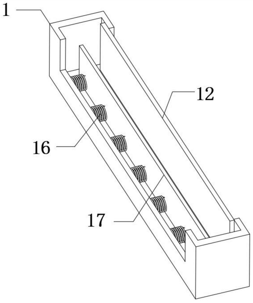
[0035] refer to Figure 5 , a digital media suspension device, comprising two limit frames 1 and chute 23, the outer walls of the same side of the two limit frames 1 are fixedly connected with connecting plates 8, and the outer walls of the two connecting plates 8 are fixedly connected with Hydraulic cylinder 2, the two hydraulic cylinders 2 are connected with a synchronous hydraulic system, the other ends of the two hydraulic cylinders 2 are fixedly connected with an air plate 10, and the outer walls of one side of the two air plates 10 are provided with split holes 21 at equal distances, each The outer walls of each split hole 21 are fixedly connected with a suction cup 9, the top outer wall of the gas plate 10 is fixedly connected with a vacuum pump 13, and the vacuum end of the vacuum pump 13 is fixedly connected with an air extraction pipe 15, and the top outer wall of the air plate 10 has an air extraction hole 18. , the other end of the air extraction pipe 15 is fixedly...


PUM


Abstract

The invention belongs to the technical field of digital media installation, particularly relates to a digital media suspension device. In order to solve the problems that when an existing digital media is suspended, the digital media is generally singly suspended on a lifting ring through a hook, in the suspension mode, the suspended digital media is likely to be in a suspended state, when the digital media is slightly touched, the digital media is likely to shift in position, so that the digital media is in an unstable state after being suspended, the following scheme is provided presently. According to the scheme, the digital media suspension device comprises two limiting frames and a sliding groove, connecting plates are fixedly connected to the outer walls of the same sides of the twolimiting frames, hydraulic cylinders are fixedly connected to the outer walls of the two connecting plates, the two hydraulic cylinders are connected with a synchronization hydraulic system, and the other ends of the two hydraulic cylinders are fixedly connected with air plates. According to the digital media suspension device, flow guide plates and a flow dividing pipe are arranged, during vacuumizing operation, the flow guide plates disperse suction force to all positions of flow dividing holes so that the interiors of all the suction cups can be vacuumized, and the vacuumizing effect is improved.

Description

technical field [0001] The invention relates to the technical field of digital media installation, in particular to a digital media suspension device. Background technique [0002] Digital media belongs to the category of engineering disciplines, and refers to information carriers that record, process, disseminate, and acquire processes in the form of binary numbers; these carriers include digitized text, graphics, images, sounds, video images, and animations. The expression media (coding) of sensory media, etc., are commonly referred to as logical media, as well as physical media for storage, transmission, and display of logical media. Suspension devices are required for the suspension installation of digital media. [0003] When the existing digital media is suspended, it is generally hung on the ring by a single hook. This kind of suspension method is likely to cause the suspended digital media to be in a suspended state. When it is slightly touched, it is easy to There ...

Claims


Application Information

Patent Timeline
IPC IPC(8): F16M13/02F16M11/04
CPCF16M13/022F16M11/04
Inventor 汪凯
Owner XUCHANG UNIV
Why Eureka
Try Eureka