Power equipment box fixing mechanism

A technology of electric equipment box and fixing mechanism, which is applied to mechanical equipment, electrical components, supporting machines, etc., can solve problems such as troublesome disassembly and replacement, affecting installation efficiency, and troublesome bolting work.

Active Publication Date: 2020-10-30
大唐万宁天然气发电有限责任公司
View PDF7 Cites 2 Cited by
  • Summary
  • Abstract
  • Description
  • Claims
  • Application Information

AI Technical Summary

Problems solved by technology

[0002] The existing installation methods of the power equipment box include two types. The first one is to install on the flat ground or the surface of the object. The staff can directly place the power equipment box on the flat ground or the surface of the object, and then bolt the power equipment box Fixed; the second is to install on uneven ground or the surface of objects. The staff can use the installation plate matched with the power equipment box for fixed installation. First fix the installation plate at a certain position, and then place the power equipment box on the The installation plate is fixed and connected by bolts; since the installation position of the power equipment box is often on an uneven surface, the second installation method is often used, and the second installation method needs to be bolted to the installation plate first. Make a fixed connection, and then use bolts to fix the power equipment box on the mounting plate. The two bolt fixing work is very troublesome, which seriously affects the installation efficiency, and also brings great trouble to the subsequent disassembly and replacement.

Method used


Image

  • Power equipment box fixing mechanism
  • Power equipment box fixing mechanism
  • Power equipment box fixing mechanism

Examples


Embodiment Construction

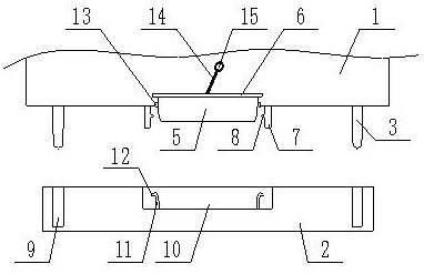
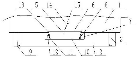
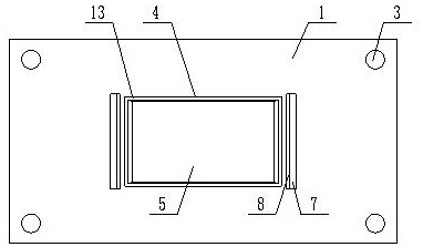
[0028] The present invention is specifically described below in conjunction with accompanying drawing, as Figure 1-4 shown;

[0029] The inventive point of the present application is that an opening 4 is provided on the bottom surface of the power equipment box, the opening is a rectangular opening, the opening communicates with the inner cavity of the power equipment box, and a plug body 5 is installed at the opening, and the plug body The shape and size match the shape and size of the opening, the upper surface of the plug body is fixedly connected to the baffle 6, and the upper surface of the baffle is fixedly installed with a pull ring;

[0030] The inventive point of the present application is also that two connection plates 7 are fixedly installed on the bottom surface of the power equipment box, the two connection plates are parallel to each other, the two connection plates are located on the left and right sides of the opening and are symmetrical about the opening, th...


PUM


Abstract

The invention discloses a power equipment box fixing mechanism. The power equipment box fixing mechanism comprises a power equipment box and a matched mounting plate, wherein support legs are arrangedon the bottom surface of the power equipment box; the four support legs are positioned at the four corners of the bottom surface of the power equipment box respectively; an opening is formed in the bottom surface of the power equipment box; the opening is a rectangular opening; the opening is in communication with the inner cavity of the power equipment box; a plug body is arranged in the opening; the plug body is matched with the opening in shape and size; the upper surface of the plug body is fixedly connected with a baffle plate; and a pulling ring is fixedly arranged on the upper surfaceof the baffle plate. The power equipment box fixing mechanism has the beneficial effects of simple structure and rapidness and convenience in mounting.

Description

technical field [0001] The invention relates to the technical field of electric equipment, in particular to a fixing mechanism for an electric equipment box. Background technique [0002] The existing installation methods of the power equipment box include two types. The first one is to install on the flat ground or the surface of the object. The staff can directly place the power equipment box on the flat ground or the surface of the object, and then bolt the power equipment box Fixed; the second is to install on uneven ground or the surface of objects. The staff can use the installation plate matched with the power equipment box for fixed installation. First fix the installation plate at a certain position, and then place the power equipment box on the The installation plate is fixed and connected by bolts; since the installation position of the power equipment box is often on an uneven surface, the second installation method is often used, and the second installation meth...

Claims


Application Information

Patent Timeline
Patent Type & Authority Applications(China)
IPC IPC(8): F16M13/02H02B1/46
CPCF16M13/027H02B1/46
Inventor 张瑞雪
Owner 大唐万宁天然气发电有限责任公司
Why Eureka
Try Eureka