
Blade structure of a drying drum

A technology of blade structure and drum, which is applied in drying, drying solid materials, lighting and heating equipment, etc., can solve the problems of affecting thermal efficiency, sticking of lifting blades, and easy bonding on dead corners, so as to improve thermal efficiency and reduce The effect of mud content

Active Publication Date: 2021-10-22
FUJIAN TIETUO MACHINERY
View PDF12 Cites 0 Cited by
  • Summary
  • Abstract
  • Description
  • Claims
  • Application Information

AI Technical Summary

Problems solved by technology

[0002] The internal blades of the existing drying drum are divided into spiral blades, material-lifting blades, and material-containing blades. Fitted structure, the material lifting blade area adopts L-shaped material lifting blade structure. When the material is wet and the mud content is high, it is easy to stick on the dead corner, or the whole material lifting blade is stuck, and the material is contained. When the blade is a T-shaped structure blade or a joint structure, the aggregate of the large material is at the bottom of the drum and does not flow with the rotation of the drum. The above two blades may affect the thermal efficiency or cause equipment failure in practical applications. Sometimes it is necessary to manually adjust the blades in the drum. Cleaning up, low work efficiency

Method used


Image

  • Blade structure of a drying drum
  • Blade structure of a drying drum
  • Blade structure of a drying drum

Examples


Embodiment Construction

[0031] In order to better explain the present invention and facilitate understanding, the present invention will be described in detail below with reference to the accompanying drawings and through specific embodiments.

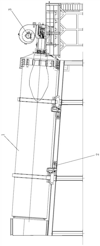
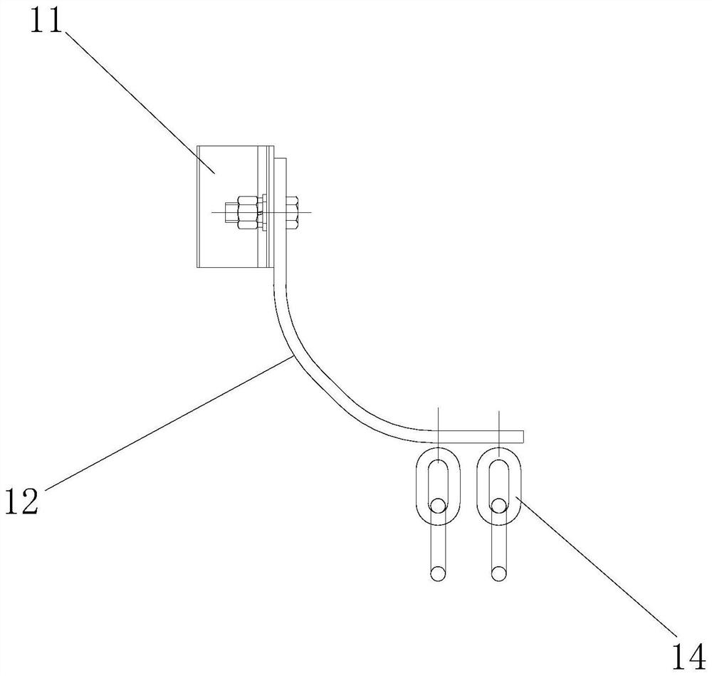
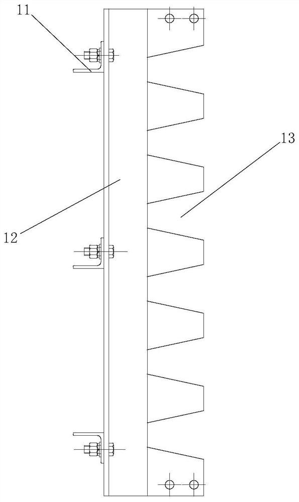
[0032] A blade structure of a drying drum, such as Figure 1-Figure 11 As shown, it includes a number of tooth-shaped material-lifting blades and a number of cradle-type material-containing blades connected to the inner wall of the drum 1 in an annular array; the tooth-shaped material-lifting blades are located on the side near the feeding end of the drum 1, The cradle-type material-containing blade is located on the side close to the discharge end of the drum 1 .

[0033] Further, the outer wall of the drum 1 is connected with a rolling ring; the rolling ring is matched with the driving mechanism 2 arranged on the frame, the driving mechanism is a deceleration motor, and the output end of the deceleration motor is connected with a supporting wheel, so The o...


PUM


Abstract

The invention relates to a blade structure of a drying drum, which comprises several tooth-shaped material-lifting blades and several cradle-shaped material-containing blades connected to the inner wall of the drum in an annular array; One side of the material end, the side of the cradle-shaped material-containing blade close to the discharge end of the drum. The tooth-shaped lifting blade of the present invention adopts the combination of chain and tooth groove. The tooth-shaped lifting blade lifts the aggregate to a high place and falls with the rotation of the drum, and the aggregate falls and impacts the chain, and the bonded bone It can separate the soil from the aggregate or aggregate, prevent the aggregate from sticking to the lifting blade, and reduce the mud content of the aggregate. The cradle-type material-containing blade of the present invention adopts the combination of cradle blade, bracket, upper baffle plate and material lifting plate. Isolation from the flame of the burner prevents the aggregate from coming into contact with the flame, so as to obtain the maximum material content.

Description

technical field [0001] The invention relates to the technical field of drying drums, in particular to a blade structure of a drying drum. Background technique [0002] The existing internal blades of the drying drum are divided into spiral blades, material-extracting blades, and material-containing blades, which are arranged in the radial direction of the circumference. Usually, the material-extracting blades adopt an L-shaped structure, and the material-containing blades are T-shaped structure blades or Combined structure, the L-shaped lifting blade structure is adopted in the material extraction blade area. When the material is wet and the mud content is high, it is easy to bond on the dead corner, or the entire material extraction blade sticks, and the material contains the jelly and the material. When the blade is a T-shaped structure blade or a combined structure, the aggregate of the large material is at the bottom of the drum and does not flow with the rotation of the...

Claims


Application Information

Patent Timeline
Patent Type & Authority Patents(China)
IPC IPC(8): F26B25/04
CPCF26B25/04
Inventor 高国强杜金鑫揭文忠陈聪永
Owner FUJIAN TIETUO MACHINERY
Learn More