
Underground optical cable routing device and underground routing method based on communication design

An underground optical cable and communication design technology, applied in the field of communication engineering, can solve the problems of limited size and low efficiency of optical cable installation

Active Publication Date: 2020-10-30
NANNING COLLEGE FOR VOCATIONAL TECH
View PDF8 Cites 0 Cited by
  • Summary
  • Abstract
  • Description
  • Claims
  • Application Information

AI Technical Summary

Problems solved by technology

[0005] However, in the prior art, when optical cables (cables) are laid underground, most of them are pulled by hoists, and the guide wheels are placed manually following the movement of the optical cables. By placing the guide wheels, the friction between the optical cables and the ground is reduced. To prevent damage due to friction with the ground due to its own weight, but because the size of the pipe gallery (or cable tunnel) is limited by geographical conditions, in some places the size is relatively small, and the staff can only bend the work, resulting in low cable installation efficiency

Method used


Image

  • Underground optical cable routing device and underground routing method based on communication design
  • Underground optical cable routing device and underground routing method based on communication design
  • Underground optical cable routing device and underground routing method based on communication design

Examples


Embodiment Construction

[0042] The following will clearly and completely describe the technical solutions in the embodiments of the present invention with reference to the accompanying drawings in the embodiments of the present invention. Obviously, the described embodiments are only some, not all, embodiments of the present invention.

[0043] In describing the present invention, it is to be understood that the terms "one end", "the other end", "both ends", "between", "middle", "lower", "upper end", "lower end" etc. indicate The orientation or positional relationship is based on the orientation or positional relationship shown in the drawings, and is only for the convenience of describing the present invention and simplifying the description, rather than indicating or implying that the referred device or element must have a specific orientation, be configured in a specific orientation, and operation, and therefore should not be construed as limiting the invention.

[0044] In the description of the ...


PUM


Abstract

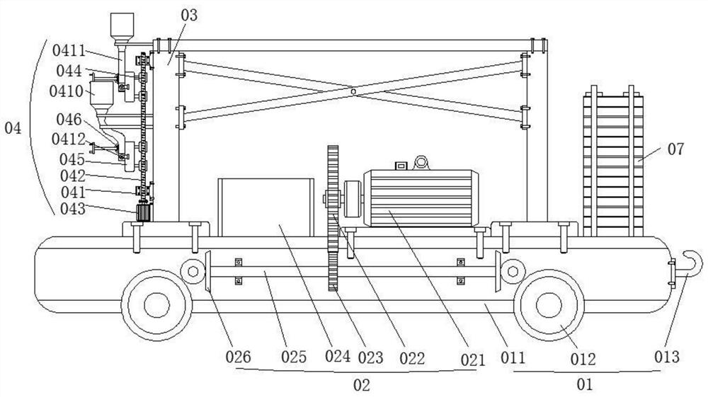
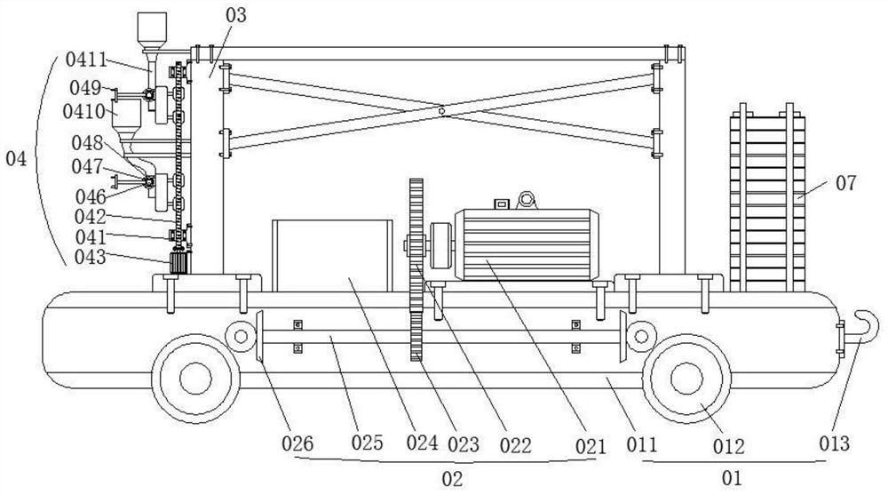
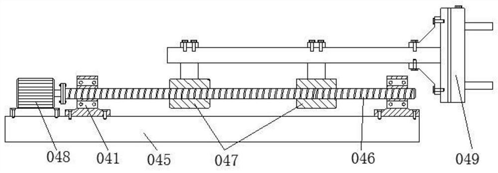
The invention discloses an underground optical cable routing device and an underground routing method based on communication design, which are used for solving the problems of low underground routingefficiency and high labor intensity of an optical cable. The device comprises a mounting frame, wherein walking wheels are rotationally mounted on the mounting frame; a driving motor used for drivingthe walking wheels to rotate is further mounted on the mounting frame, or the mounting frame is pulled by a pulling rope to be driven to move; a mounting plate is further mounted on the mounting frame; first lead screws are mounted on the left side and the right side of the mounting plate correspondingly; each first lead screw is sleeved with at least one first lead screw nut; the first lead screwnut is provided with a storage bin used for storing a roller in a matched mode; the first lead screw nut is further fixedly provided with a pushing air cylinder used for pushing the lowermost rollerinto a wire hanging frame on the inner wall of the pipe gallery; and the first lead screw nut is further provided with a clamping part which can extend to the position above the wire hanging frame onthe inner wall of the pipe gallery and is used for clamping an optical cable.

Description

technical field [0001] The invention belongs to the technical field of communication engineering; in particular, it relates to an underground optical cable routing device and an underground routing method based on communication design. Background technique [0002] With the rapid development of urban construction, transformation and informatization, the number of new construction, reconstruction and expansion projects of communication optical cable lines is increasing, and the construction volume of optical cables is increasing. Communication optical cables in cities and towns are required to be laid by underground communication pipelines. When the existing communication cables are laid underground, the cables are usually placed directly in the communication pipeline or in the pipe gallery. Due to the shortcomings of the communication pipeline, such as small capacity, difficult expansion, and limited fiber and cable division, most of them currently use Fiber optic cable layi...

Claims


Application Information

Patent Timeline
Patent Type & Authority Applications(China)
IPC IPC(8): G02B6/50G02B6/44
CPCG02B6/50G02B6/545
Inventor 黄继文
Owner NANNING COLLEGE FOR VOCATIONAL TECH
Learn More