Supercharge Your Innovation With Domain-Expert AI Agents!

Objective optical system for endoscope and endoscope

A technology for optical systems and endoscopes, applied in the field of objective optical systems for endoscopes and endoscopes, can solve the problems of short total length and achieve good optical performance

Pending Publication Date: 2020-10-30
FUJIFILM CORP
View PDF3 Cites 0 Cited by
  • Summary
  • Abstract
  • Description
  • Claims
  • Application Information

AI Technical Summary

Problems solved by technology

[0008] However, the lens systems described in Patent Document 1, Patent Document 2, and Patent Document 3 cannot be said to have a sufficiently short total length.

Method used


Image

  • Objective optical system for endoscope and endoscope
  • Objective optical system for endoscope and endoscope
  • Objective optical system for endoscope and endoscope

Examples


Embodiment 1

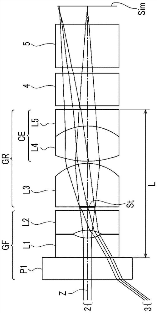
[0087] Represent the structure of the endoscope object lens optical system of embodiment 1 and the sectional view of light beam such as figure 1 As shown, the illustration method is the same as above, so a part of repeated description is omitted here. The objective optical system for an endoscope of Example 1 includes a front group GF having a negative refractive power, an aperture stop St, and a rear group GR having a positive refractive power in this order from the object side to the image side. The front group GF includes a parallel plane plate P1, a first lens L1, and a second lens L2 in this order from the object side to the image side. The rear group GR includes a third lens L3, a fourth lens L4, and a fifth lens L5 in this order from the object side to the image side. The first lens L1, the second lens L2, and the fifth lens L5 are negative lenses. The third lens L3 and the fourth lens L4 are positive lenses. The first lens L1, the second lens L2, and the third lens ...

Embodiment 2

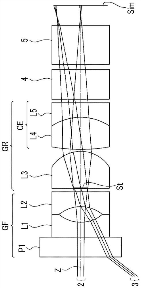
[0100] A cross-sectional view showing the structure and light beams of the endoscope objective optical system of Embodiment 2 is shown in figure 2 middle. The objective optical system for endoscope of Example 2 has the same configuration as the objective optical system for endoscope of Example 1 in outline. Regarding the objective optical system for an endoscope of Example 2, the basic lens data are shown in Table 3, the specifications are shown in Table 4, and the aberration diagrams are shown in Table 4. Figure 5 middle.

[0101] [table 3]

[0102] Example 2

[0103]

[0104]

[0105] [Table 4]

[0106] Example 2

[0107] f 0.34 Bf 0.72 FNo. 4.27 2ω(°) 105.4

Embodiment 3

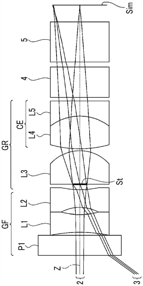
[0109] A cross-sectional view showing the structure and light beams of the endoscope objective optical system of Embodiment 3 is shown in image 3 middle. The objective optical system for endoscope of Example 3 has the same configuration as the objective optical system for endoscope of Example 1 in outline. Regarding the objective optical system for an endoscope of Example 3, the basic lens data are shown in Table 5, the specifications are shown in Table 6, and the aberration diagrams are shown in Table 6. Image 6 middle.

[0110] [table 5]

[0111] Example 3

[0112] sn R D Nd vd 1 ∞ 0.2000 1.88299 40.78 2 ∞ 0.0300 3 -1.4800 0.1756 1.67790 55.34 4 0.8012 0.0700 5 -0.4114 0.1756 1.72916 54.68 6 0.9155 0.0550 7(St) ∞ 0.0000 8 ∞ 0.3327 1.85150 40.78 9 -0.4093 0.0200 10 1.1541 0.3250 1.95375 32.32 11 -0.5000 0.1500 1.98613 16.48 12 ∞ 0.0350 13 ∞ 0...


PUM


Abstract

The invention provides an objective optical system for an endoscope and an endoscope provided with the objective optical system for the endoscope. The objective optical system for the endoscope has awide viewing angle, is small in size and maintains good optical performance. The objective optical system for an endoscope consists of, in order from an object side, a negative front group, an aperture stop, and a positive rear group. A lens closest to the object side in the front group is a negative lens concave toward an image side, and a lens positioned second from the object side in the frontgroup is a negative lens concave toward the object side. The rear group includes a cemented lens in which a positive lens and a negative lens are cemented in order from the object side. The objectiveoptical system for an endoscope satisfies predetermined conditional expressions relating to a focal length of a whole system, a focal length of the front group, and a distance from a lens surface closest to the object side to a lens surface closest to the image side.

Description

technical field [0001] The invention relates to an objective optical system for an endoscope and the endoscope. Background technique [0002] Conventionally, various lens systems have been proposed as objective optical systems for endoscopes. Patent Document 1 below describes an endoscope objective optical system including, in order from the object side, a front group having a negative refractive power, an aperture stop, and a rear group having a positive refractive power. Patent Document 2 below describes an endoscope objective lens including a front group having a negative refractive power, an aperture stop, and a rear group having a positive refractive power in order from the object side. The following Patent Document 3 describes an objective optical system which is composed of a first group having two lenses with negative and positive refractive powers arranged in negative and positive refractive powers, a diaphragm, and a second group with positive refractive powers in...

Claims


Application Information

Patent Timeline
IPC IPC(8): G02B13/00G02B13/06G02B23/24A61B1/00A61B1/005
CPCG02B13/006G02B13/06G02B23/243A61B1/00163A61B1/00064A61B1/00071A61B1/005A61B1/00188A61B1/00096G02B13/0045A61B1/00174G02B27/0025G02B9/60
Inventor 井上和纪
Owner FUJIFILM CORP
Features
  • R&D
  • Intellectual Property
  • Life Sciences
  • Materials
  • Tech Scout
  • Unparalleled Data Quality
  • Higher Quality Content
  • 60% Fewer Hallucinations
Learn More