
Plasma processing equipment

A plasma and equipment technology, applied in the field of plasma processing equipment, can solve the problems affecting the uniformity, consumption, wafer edge etching direction and rate change of wafer processing, etc., and achieve the effect of improving uniformity

Active Publication Date: 2020-10-30
ADVANCED MICRO FAB EQUIP INC CHINA
View PDF6 Cites 0 Cited by
  • Summary
  • Abstract
  • Description
  • Claims
  • Application Information

AI Technical Summary

Problems solved by technology

[0003] In the plasma etching equipment, the pedestal is connected to the radio frequency source as an electrode, and a focus ring surrounding the substrate is also provided around the pedestal. The focus ring is used to adjust the electric field distribution around the wafer to ensure the uniformity of wafer etching, while the focus The upper surface of the ring is exposed to the plasma environment, which will be consumed as the etching process progresses, which will lead to changes in the electric field around the wafer, resulting in changes in the etching direction and rate at the edge of the wafer, affecting the uniformity of wafer processing

Method used


Image

  • Plasma processing equipment
  • Plasma processing equipment

Examples


Embodiment Construction

[0024] In order to make the above objects, features and advantages of the present invention more comprehensible, specific implementations of the present invention will be described in detail below in conjunction with the accompanying drawings.

[0025] In the following description, a lot of specific details are set forth in order to fully understand the present invention, but the present invention can also be implemented in other ways different from those described here, and those skilled in the art can do without departing from the connotation of the present invention. By analogy, the present invention is therefore not limited to the specific examples disclosed below.

[0026] In the plasma etching equipment, the base is connected to the radio frequency source as an electrode, the wafer to be processed is set on the base surface, and the bias radio frequency power is used to control the thickness of the sheath layer formed on the wafer surface and the focus ring surface, The ...


PUM


Abstract

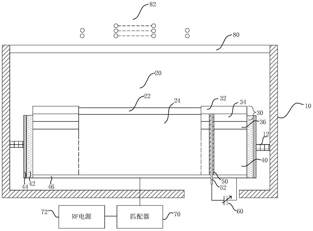
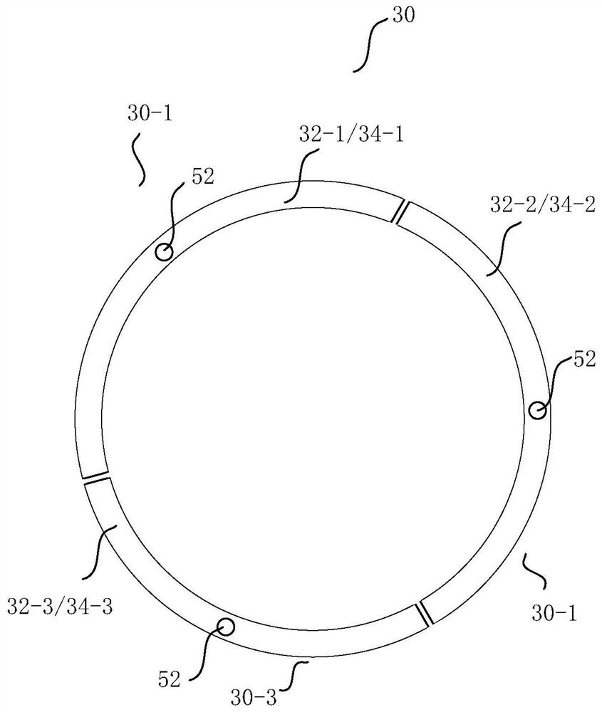
The invention provides plasma processing equipment. An edge ring around a conductive base consists of a plurality of independent arc parts; each arc part comprises an arc-shaped ceramic part of whichthe upper part is exposed to plasma and an arc-shaped conductive part positioned below the arc-shaped ceramic part; the plurality of arc-shaped conductive parts jointly form a coupling ring; the plurality of arc-shaped ceramic parts jointly form a focusing ring; and each arc-shaped part is connected with a driving part and drives each arc-shaped part to move along a direction perpendicular to theconductive base. Therefore, the height of each section of the edge ring can be adjusted in a segmented manner, so that the loss of the focusing ring in the edge ring is compensated in a segmented manner along with an etching process, the height of each section of focusing ring is accurately compensated, and the wafer processing uniformity is improved.

Description

technical field [0001] The invention relates to the field of semiconductor processing equipment, in particular to a plasma processing equipment. Background technique [0002] Plasma processing equipment generates plasma by means of radio frequency coupling discharge, and then uses plasma for deposition, etching and other processing processes. [0003] In the plasma etching equipment, the base is connected to the radio frequency source as an electrode, and a focus ring surrounding the substrate is also provided around the base. The focus ring is used to adjust the electric field distribution around the wafer to ensure the uniformity of wafer etching, while the focus The upper surface of the ring is exposed to the plasma environment, which will be consumed as the etching process progresses, which will lead to changes in the electric field around the wafer, resulting in changes in the etching direction and rate at the edge of the wafer, affecting the uniformity of wafer process...

Claims


Application Information

Patent Timeline
Patent Type & Authority Applications(China)
IPC IPC(8): H01J37/32
CPCH01J37/32009H01J37/32431
Inventor 杨宏旭赵馗倪图强
Owner ADVANCED MICRO FAB EQUIP INC CHINA
Learn More