Condition switching method and corresponding user equipment

A technology of user equipment and conditions, applied in the direction of electrical components, wireless communication, etc.

Pending Publication Date: 2020-10-30
SHARP KK
View PDF0 Cites 2 Cited by
  • Summary
  • Abstract
  • Description
  • Claims
  • Application Information

AI Technical Summary

Problems solved by technology

[0004] The purpose of the embodiments of the present disclosure is to propose a solution to the problem of implementing the CHO technology in the NR system and the LTE sys

Method used


Image

  • Condition switching method and corresponding user equipment
  • Condition switching method and corresponding user equipment
  • Condition switching method and corresponding user equipment

Examples


Embodiment 1

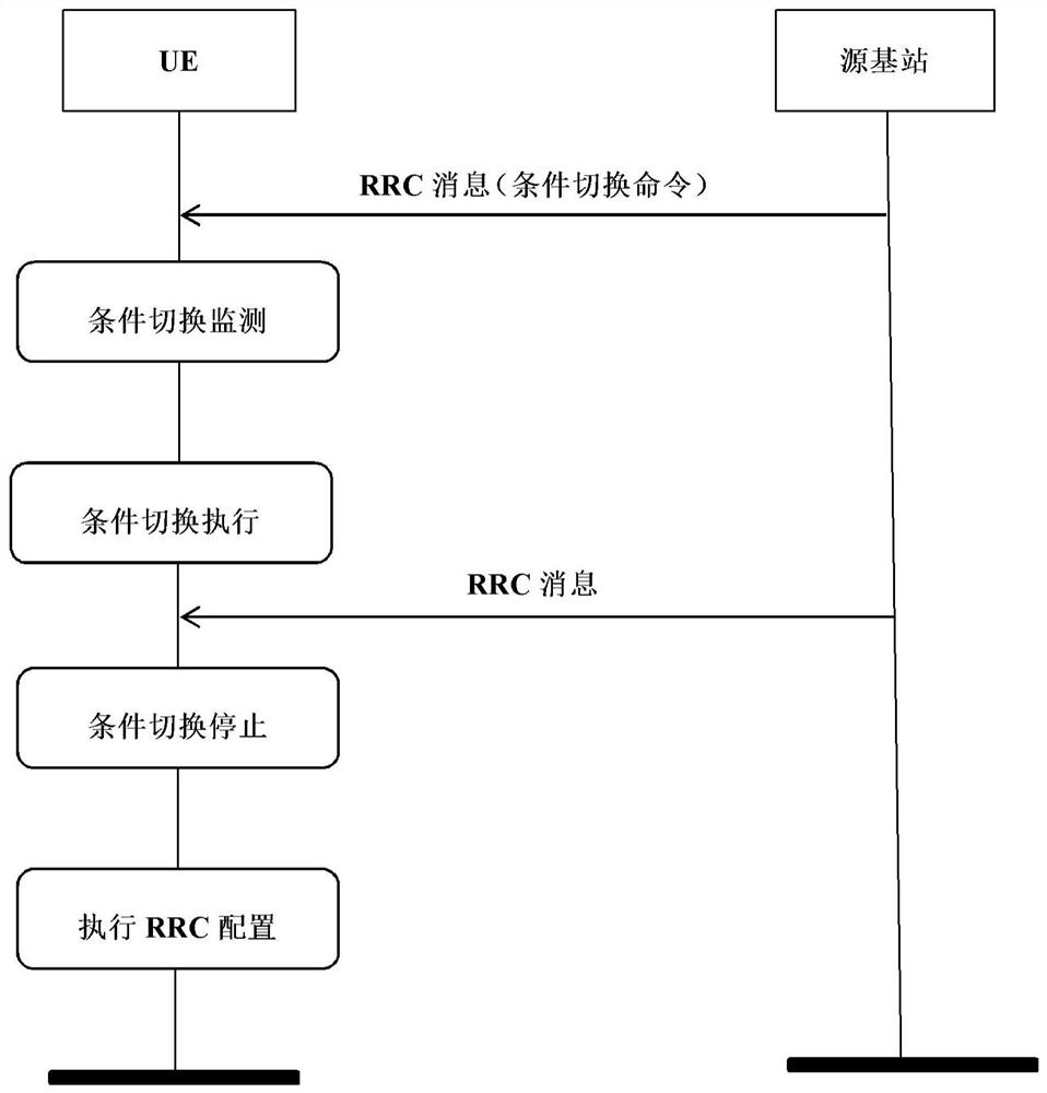
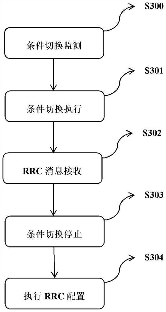
[0046] In this embodiment, when the UE performing the conditional handover receives the RRC message from the source base station, the UE stops the ongoing conditional handover process, and applies or executes the received RRC message. Wherein, executing conditional switching may also be described as initiating conditional switching. Next, use figure 2 as well as image 3 to describe the process.

[0047] Step S301: Initiate conditional switching (conditional switching execution step).

[0048] The initiating conditional handover is initiated when the UE detects that the handover condition in the saved conditional handover configuration is met. The conditional handover configuration and the handover condition are associated with a target cell. Preferably, the operation of initiating conditional handover includes one or more of the following: start timer T304; execute the target cell RRC configuration in the conditional handover configuration corresponding to the target cel...

Embodiment 2

[0064] In this embodiment, when the UE performing the conditional handover receives the RRC message from the source base station, the UE continues the ongoing conditional handover process without applying or executing the received RRC message. Wherein, the conditional handover being executed may also be described as the conditional handover being initiated or the timer T304 for the conditional handover being running. Next, use Figure 4 as well as Figure 5 to describe the process.

[0065] Step S501: Initiate conditional switching (conditional switching execution step).

[0066] The initiating conditional handover is initiated when the UE detects that the handover condition in the saved conditional handover configuration is met. The conditional handover configuration and the handover condition are associated with a target cell. Preferably, the operation of initiating conditional handover includes one or more of the following: start timer T304; execute the target cell RRC ...

Embodiment 3

[0075] In this embodiment, after the conditional handover is initiated, the UE does not process the RRC message from the source cell or to be sent to the source cell, which is similar to the second embodiment. Execute on UE. That is to say, during the conditional handover process (the timer T304 for the conditional handover is running), the RRC message from the source cell or to be sent to the source cell is no longer processed.

[0076] Step 1: Initiate a conditional switch.

[0077] The operation and process of initiating a conditional switch are the same as those in the foregoing embodiments, and will not be repeated here.

[0078] Step 2: Suspend (suspend) Signaling Radio Bearer 1 (Signalling Radio Bearer 1, SRB1). Optionally, reestablishing PDCP or RLC corresponding to the SRB1 is also included. The RRC here refers to the RRC associated with the source cell, and the PDCP or RLC refers to the PDCP or RLC associated with the source cell.

[0079] Step 3: after the random ...


PUM


Abstract

The invention provides a condition switching method executed by user equipment and the corresponding user equipment. The conditional switching method executed by user equipment comprises the followingsteps: a conditional switching monitoring step: the user equipment (UE) receives a radio resource control (RRC) message containing a conditional switching command from a source base station, stores conditional switching configuration in the conditional switching command, and monitors whether a switching condition is met or not according to the switching condition; a condition switching executionstep: condition switching is initiated when the UE monitors that the switching condition in the stored condition switching configuration is satisfied; an RRC message receiving step: the UE that is performing conditional switching receives an RRC message from the source base station; a condition switching stop step: the UE stops the ongoing condition switching process; an RRC configuration step: the UE executes the corresponding configuration according to the configuration in the RRC message received in the ongoing condition switching process.

Description

technical field [0001] The present disclosure relates to the technical field of wireless communication, and more specifically, the present disclosure relates to a conditional handover method and a corresponding user equipment. Background technique [0002] In June 2018, a new research project on 5G technical standards was approved at the 3rd Generation Partnership Project (3rd Generation Partnership Project: 3GPP) RAN#80 plenary meeting (see non-patent literature: RP-181433: New WID on NR (New Radio) mobility enhancements). In addition, there is another new research project for Release 16 (see non-patent literature: RP-190272: WID for Even further Mobility enhancement in E-UTRAN (Evolved-Universal Terrestral Radio Access Network)). One of the research purposes of these two projects is to find one of the ways to meet the mobility needs in the network: seamless handover, that is, to meet the handover interruption time of 0 milliseconds or close to 0 milliseconds during the ce...

Claims


Application Information

Patent Timeline
IPC IPC(8): H04W36/00H04W36/08H04W36/30
CPCH04W36/0005H04W36/0058H04W36/0085H04W36/08H04W36/30H04W36/00
Inventor 常宁娟刘仁茂
Owner SHARP KK
Why Eureka
Try Eureka