Objective optical system for endoscope

A technology for optical systems and endoscopes, which is applied in the field of objective lens optical systems for endoscopes, and can solve problems such as narrowing depth of field

Active Publication Date: 2020-10-30
OLYMPUS CORP
View PDF10 Cites 3 Cited by
  • Summary
  • Abstract
  • Description
  • Claims
  • Application Information

AI Technical Summary

Problems solved by technology

However, the depth of field tends to become narrower as the number of pixels of the image sensor increases

Method used


Image

  • Objective optical system for endoscope
  • Objective optical system for endoscope
  • Objective optical system for endoscope

Examples


Embodiment approach

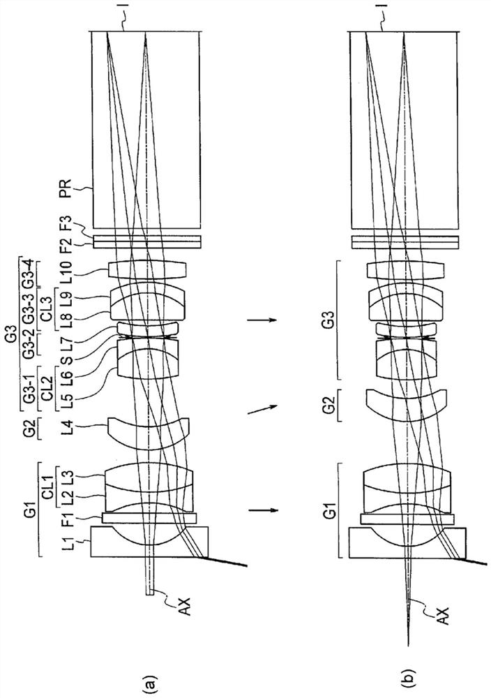
[0035] figure 1 (a) is a lens cross-sectional view in a normal observation state of the endoscope objective optical system according to the embodiment. figure 1 (b) is a lens cross-sectional view of the endoscope objective optical system according to the embodiment in a close-up observation state. From the normal observation state to the close-up observation state, the second group G2 moves toward the image side.

[0036] The objective optical system for an endoscope according to this embodiment is composed of a first group G1 of negative refractive power, a second group G2 of positive refractive power, and a third group G3 of positive refractive power arranged in this order from the object side. Group 1 G1 and Group 3 G3 are fixed, and Group 2 G2 moves. The first group G1 has at least two lenses with negative refractive power, and the third group G3 consists of the positive refractive power group 3-1 G3-1 and the negative refractive power group 3-2 G3- arranged in order f...

Embodiment 1

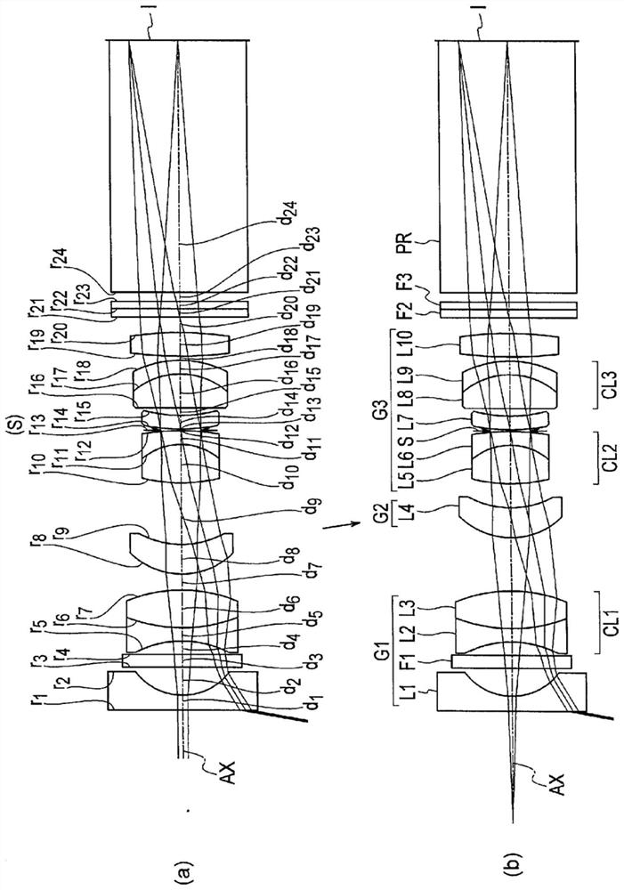
[0144] figure 2 (a) is a lens cross-sectional view of the endoscope objective optical system according to Example 1 in a normal observation state. figure 2 (b) is a lens cross-sectional view of the endoscope objective optical system according to Example 1 in a close-up observation state.

[0145] The objective optical system for an endoscope according to Example 1 is composed of a first group G1 of negative refractive power, a second group G2 of positive refractive power, and a third group G3 of positive refractive power arranged in this order from the object side. The first group G1 and the third group G3 are fixed, and the second group G3 moves. In the close observation state, the second group G2 moves toward the image side.

[0146] The first group G1 of negative refractive power has a plano-concave first negative lens L1 with the plane facing the object side, an infrared cut filter F1, a biconcave second negative lens L2, and a biconvex second negative lens L2 arranged...

Embodiment 2

[0152] Figure 4 (a) is a lens cross-sectional view of the endoscope objective optical system according to Example 2 in a normal observation state. Figure 4 (b) is a lens cross-sectional view of the endoscope objective optical system according to Example 2 in a close-up observation state.

[0153] The objective optical system for an endoscope according to Example 2 is composed of a first group G1 of negative refractive power, a second group G2 of positive refractive power, and a third group G3 of positive refractive power arranged in this order from the object side. The first group G1, the third group G3 are fixed, and the second group G2 moves. In the close observation state, the second group G2 moves toward the image side.

[0154] The first group G1 of negative refractive power has a first negative meniscus lens L1 with a convex surface facing the object side, an infrared cut filter F1, a biconcave second negative lens L2, and a biconvex third negative lens L2 arranged i...


PUM


Abstract

The present invention provides a high-performance objective optical system for an endoscope that can accommodate an increase in the number of pixels without sacrificing on back focus. The objective optical system for an endoscope comprises, in order from the object side: a first group (G1) having a negative refractive power; a second group (G2) having a positive refractive power; and a third group(G3) having a positive refractive power. The first group (G1) and the third group (G3) are fixed and the second group (G2) is movable. The first group G1 has at least two lenses having a negative refractive power. The third group (G3) comprises, in order from the object side: a first group (G3-1) having a positive refractive power; a second group (G3-2) having a negative refractive power; a thirdgroup (G3-3) having a positive refractive power; and a fourth group (G3-4) having a positive refractive power.

Description

technical field [0001] The invention relates to an objective lens optical system for an endoscope. In particular, it relates to an objective optical system for an endoscope with a long back focal length. An objective optical system for an endoscope having a long back focal length is preferable for endoscope devices used in the medical field, industrial field, and the like, for example. Background technique [0002] Endoscopes are devices widely used in medical and industrial fields. Particularly in the medical field, an endoscope inserted into a body cavity acquires images of the inside of the body cavity. In this way, endoscopes in the medical field are used for diagnosis and treatment of observed parts. [0003] Conventionally, by setting an appropriate Fno (F-number) and an appropriate focus position in an objective optical system, a focused image can be acquired from a near point to a far point. However, the depth of field tends to become narrower as the number of pi...

Claims


Application Information

Patent Timeline
Patent Type & Authority Applications(China)
IPC IPC(8): G02B13/04
CPCA61B1/00188A61B1/04G02B23/243G02B9/12
Inventor 加茂裕二曾根伸彦
Owner OLYMPUS CORP
Why Eureka
Try Eureka