

Imaging lens
A camera lens and lens technology, applied in the direction of optical components, optics, instruments, etc., can solve the problems of image plane changes, high manufacturing sensitivity, etc.
- Summary
- Abstract
- Description
- Claims
- Application Information
AI Technical Summary
Problems solved by technology
Method used
Image

Examples
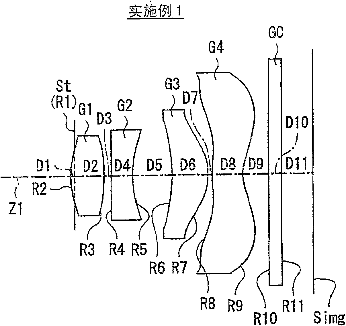
Embodiment 1
[0055] In the imaging lens according to Example 1, both surfaces of the first lens G1 , the second lens G2 , the third lens G3 , and the fourth lens G4 are all aspherical. exist Figure 5 In the basic lens data of (A), as the curvature radii of these aspheric surfaces, the numerical values of the curvature radii near the optical axis are indicated. exist Figure 5 Among the numerical values shown as aspheric data in (B), the symbol "E" indicates that the data immediately following it is a "power exponent" with base 10, indicating that it will be represented by an exponential function with base 10 multiplied by the value before "E". For example, if it is "1.0E-02", it means "1.0×10 -2 ".
[0056] As the aspheric surface data, each coefficient B in the formula representing the aspheric surface shape represented by the following formula (A) i , The value of KA. More specifically, Z represents the length (mm) of a perpendicular line drawn from a point on the aspheric sur...
PUM
 Abstract
Description
Claims
Application Information