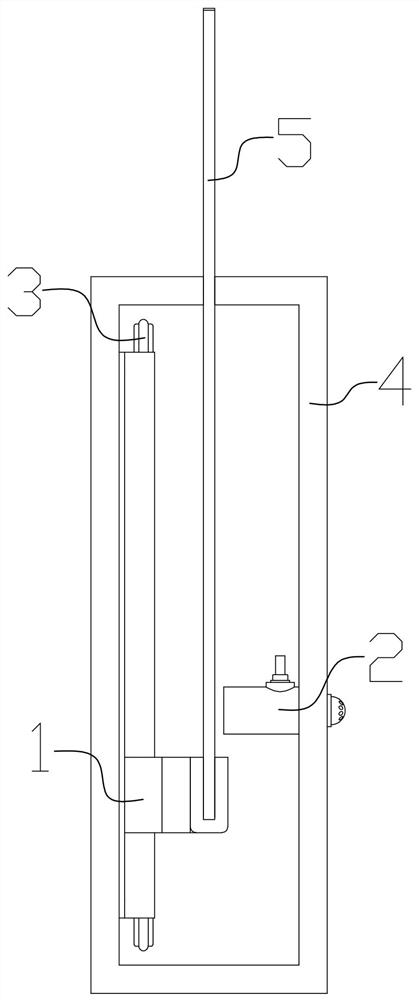
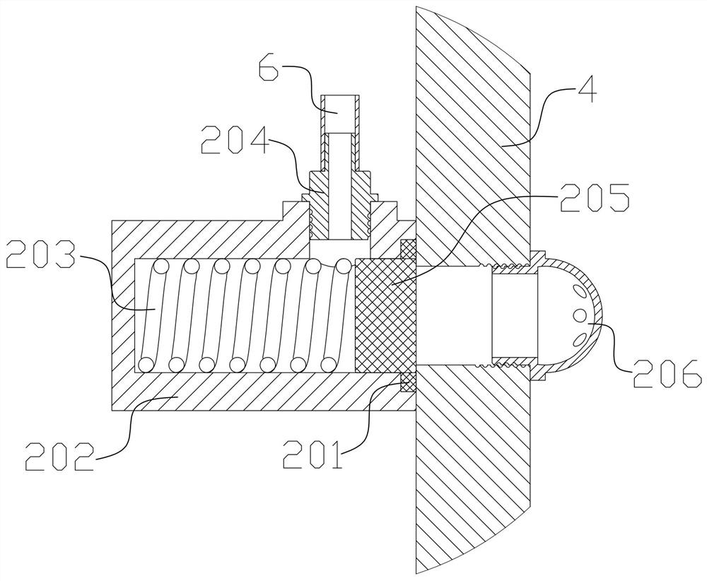
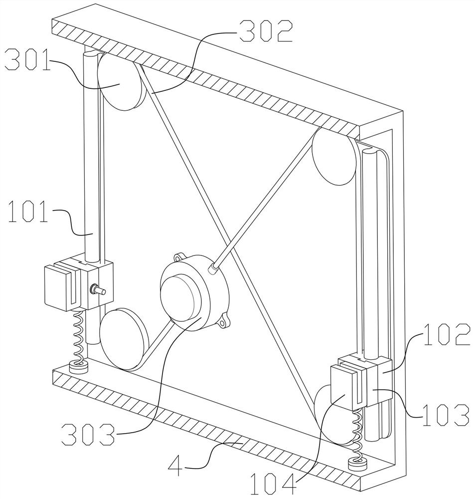
Escape device for vehicle falling into water

An escape device and vehicle technology, applied in life-saving equipment, building rescue, etc., can solve problems such as safety hazards for drivers and passengers, casualties, etc., and achieve the effects of improving survival probability, low product cost, and simple structure

Pending Publication Date: 2020-11-03
宋文琦
View PDF0 Cites 2 Cited by
  • Summary
  • Abstract
  • Description
  • Claims
  • Application Information

AI Technical Summary

Problems solved by technology

However, when the car window is smashed, the water outside the car will drive the glass fragments to quickly rush into the car, which will cause great safety hazards to drivers and passengers, and easily cause casualties.

Method used


Image

  • Escape device for vehicle falling into water
  • Escape device for vehicle falling into water
  • Escape device for vehicle falling into water

Examples


Embodiment 1

[0034] refer to Figure 7 As shown, in this embodiment, the auxiliary ejection mechanism includes a first magnet 110, a second magnet 113, and a third spring 111, and the first magnet 110 and the second magnet 113 are hollow cylinders inside. The first magnet 110 is fixedly installed on the slider 103, the second magnet 113 is fixedly installed on the inner bottom surface of the car body 4, one end of the third spring 111 is fixed on the slider 103, and the other end is fixed On the inner bottom surface of the vehicle body 4 , the third spring 111 is located on the line connecting the centers of the first magnet 110 and the second magnet 113 .

[0035] Further, the auxiliary ejection mechanism further includes a shock absorber 112 , and the shock absorber 112 is fixedly installed on the second magnet 113 .

[0036] In this embodiment, the third spring 111 is used to provide the required pulling force for the window glass 5 to fall, and the pulling force of the third spring 11...

Embodiment 2

[0038] refer to Figure 8 As shown, in this embodiment, the auxiliary ejection mechanism includes a fourth spring 109, a groove portion 1023 located on the sliding bracket 102, a raised portion 1035 located on the slider 103, and the The groove portion 1023 and the protrusion portion 1035 can cooperate with each other, the fourth spring 109 is installed in the groove portion 1023 , and the length of the groove portion 1023 is slightly longer than the protrusion portion 1035 .

[0039] In this embodiment, the fourth spring 109 provides thrust for the descent of the window glass 5, and the thrust of the fourth spring 109 will not always exist during the emergency descent of the window glass 5. When the slider 103 is completely separated from the sliding bracket 102 , the window glass 5 can only continue to fall by virtue of inertia and its own gravity. To ensure the normal operation of the device under severe conditions such as a rollover of the vehicle, there are some deficien...


PUM


Abstract

The invention discloses an escape device for a vehicle falling into water, and belongs to the technical field of escape self-rescue devices. The device is characterized in that when the vehicle fallsinto water, a water area generates large impact force or pressure on a vehicle body, and at the moment, high-pressure water flow exists around the vehicle body, and the high-pressure water flow ejectspistons of overflow switches to flow into an oil pipe; at the moment, the high-pressure water flow and air in the oil pipe form a gas-liquid mixture, the gas-liquid mixture ejects a columnar part toenable a sliding block to move relative to a sliding support, an auxiliary ejection mechanism is used for enabling the sliding block to be rapidly separated from the sliding support, the descending speed of window glass is increased, the purpose that the window glass emergently descends when the vehicle falls into water is achieved, safe escape of a driver is achieved, and the survival probabilityof a user is increased. According to the device, the execution does not need to be driven by an extra power element, the huge impact force and high-pressure water flow generated when the automobile falls into water are used as trigger signals, spring force is used as driving force, and therefore the vehicle window glass rapidly descends, energy saving and environment protecting are achieved, andthe structure is simple and reliable.

Description

technical field [0001] The invention relates to the technical field of escape self-rescue devices, in particular to an emergency lowering device for vehicle windows when a vehicle falls into water. Background technique [0002] With the development of society and the advancement of science and technology, people's material living standards have been greatly improved, and automobiles are increasingly popular in every family as a means of transportation commonly used in daily life and work. However, automobiles on the market are not widely equipped with emergency treatment devices for vehicle falling into water, which has resulted in the loss of lives of passengers in the vehicle due to failure to escape in time in recent years. [0003] In most patent documents at present, it is considered to smash the car window after the car falls into the water, and then escape from the car. However, when the window was smashed, the water outside the car drove the glass fragments to rush ...

Claims


Application Information

Patent Timeline
IPC IPC(8): A62B3/00
CPCA62B3/00
Inventor 宋文琦王海卫王祎门道新郑允凯
Owner 宋文琦
Why Eureka
Try Eureka