Absorption capacitor pre-charging circuit and peak voltage absorption circuit

A pre-charging circuit and absorbing capacitor technology, which is applied to battery circuit devices, circuit devices, collectors, etc., can solve the problems that the large peak voltage cannot be effectively suppressed, the complementary tube corresponding to the bridge arm is misconducted, and the upper and lower bridge arms are directly connected. , to prevent discharge, avoid short-circuit faults, and ensure the effect of peak voltage

Active Publication Date: 2019-06-14
SUNGROW POWER SUPPLY CO LTD
View PDF6 Cites 7 Cited by
  • Summary
  • Abstract
  • Description
  • Claims
  • Application Information

AI Technical Summary

Problems solved by technology

[0003] However, when the bridge circuit is powered on or turned on for the first time, when a power switch tube is turned on, the absorbing capacitance of its bridge arm corresponding to the complementary tube will be charged, and the current generated by the charging will generate a voltage drop on the gate resistor. In turn, the corresponding complementary tube of the bridge arm is misconducted, causing the upper and lower bridge arms to be directly connected, causing a serious short-circuit fault
[0004] In the prior art, the capacitance value of the absorption capacitor is usually reduced to avoid the situation of the upper and lower bridge arms being connected directly. However, reducing the capacitance value of the absorption capacitor will lead to the problem that the large peak voltage cannot be effectively suppressed.

Method used


Image

  • Absorption capacitor pre-charging circuit and peak voltage absorption circuit
  • Absorption capacitor pre-charging circuit and peak voltage absorption circuit
  • Absorption capacitor pre-charging circuit and peak voltage absorption circuit

Examples


Embodiment Construction

[0031] The following will clearly and completely describe the technical solutions in the embodiments of the application with reference to the drawings in the embodiments of the application. Apparently, the described embodiments are only some of the embodiments of the application, not all of them. Based on the embodiments in this application, all other embodiments obtained by persons of ordinary skill in the art without creative efforts fall within the protection scope of this application.

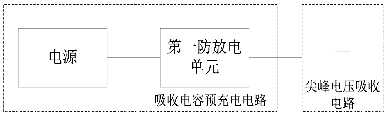
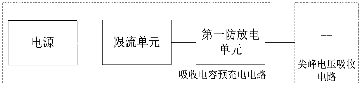
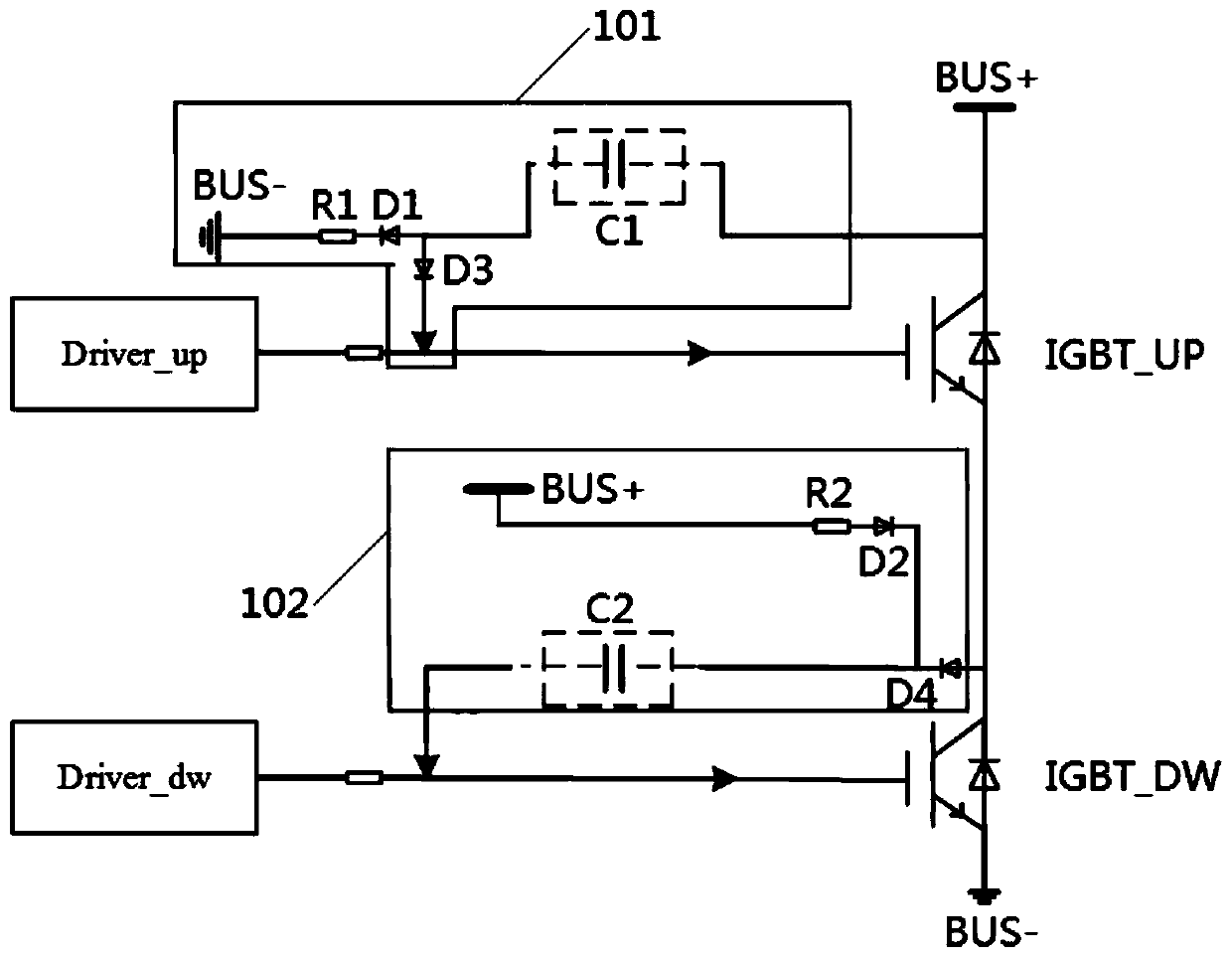
[0032] The present invention provides a pre-charging circuit for absorbing capacitors, which avoids the situation that the upper and lower bridge arms of the bridge circuit are directly connected when the bridge circuit is first powered on or turned on without reducing the capacitance value of the absorbing capacitor.

[0033] The absorption capacitor pre-charging circuit is connected with the peak voltage absorption circuit of the power switch tube in the bridge circuit; figure 1 As shown,...


PUM


Abstract

The invention provides an absorption capacitor pre-charging circuit and a peak voltage absorption circuit. Voltages of two ends of an absorption capacitor in the peak voltage absorption circuit of a power switch tube are charged to a DC bus voltage of a bridge-type circuit by a power supply, a first discharging-prevention unit is placed in a charging loop of the absorption capacitor and is used for preventing the absorption capacitor from discharging, and the absorption capacitor is pre-charged to the DC bus voltage. When the bridge-type circuit is powered on or started at the first time, thepower switch tube is instantaneously conducted, a voltage borne by a complementary pipe corresponding to a bridge arm is raised to the DC bus voltage form a half DC bus voltage, the absorption capacitor of the complementary pipe corresponding to the bridge arm is pre-charged to the DC bus voltage, so that a current flowing into a gate is zero, the voltage cannot be superposed at the gate, the direct connection of an upper bridge arm and a lower bridge arm to cause a serious short-circuit fault due to conduction by mistake is prevented, moreover, the capacitance value of the absorption capacitor is not needed to be reduced, and effective suppression on a peak voltage is ensured.

Description

technical field [0001] The invention relates to the technical field of power electronics, in particular to a precharging circuit for absorbing capacitors and a peak voltage absorbing circuit. Background technique [0002] Bridge circuits, such as two-level bridge circuits, multi-level bridge circuits, or step-up chopper circuits, etc., when the internal power switch tube is turned off, the off-current is relatively large, which will be affected by the parasitic inductance of the power loop. A high turn-off peak voltage occurs, so a peak voltage absorbing circuit needs to be provided between the collector-gate (CG) terminals of each power switch tube. Various forms of peak voltage absorbing circuits are equipped with absorbing capacitors to absorb and suppress the turn-off peak voltage, and the absorbing capacitor needs to be properly configured to effectively suppress the turn-off peak voltage. [0003] However, when the bridge circuit is powered on or turned on for the fir...

Claims


Application Information

Patent Timeline
Patent Type & Authority Applications(China)
IPC IPC(8): H02M1/34H02J7/34
Inventor 张陈香陈文杰于安博
Owner SUNGROW POWER SUPPLY CO LTD
Why Eureka
Try Eureka