
Full-automatic direction recognition and automatic correction mechanism

A direction recognition, fully automatic technology, applied in conveyor objects, transportation and packaging, sorting and other directions, can solve the problem of electronic components facing incorrectly, affecting the effect of electronic components packaging and testing, etc., to achieve a high degree of automation, Improve the effect of packaging and inspection, and reduce the effect of production cost

Pending Publication Date: 2020-11-03
金动力智能科技(深圳)有限公司
View PDF0 Cites 3 Cited by
  • Summary
  • Abstract
  • Description
  • Claims
  • Application Information

AI Technical Summary

Problems solved by technology

[0003] The invention provides a fully automatic direction recognition and automatic correction mechanism, which has the advantages of automatic direction recognition and automatic correction, and solves the problem that the vibrating plate will transport the electronic components to the indexing plate during packaging, but it will cause the electronic components to The wrong orientation of the device affects the packaging and testing of electronic components.

Method used


Image

  • Full-automatic direction recognition and automatic correction mechanism
  • Full-automatic direction recognition and automatic correction mechanism
  • Full-automatic direction recognition and automatic correction mechanism

Examples


Embodiment Construction

[0024] The following will clearly and completely describe the technical solutions in the embodiments of the present invention with reference to the accompanying drawings in the embodiments of the present invention. Obviously, the described embodiments are only some, not all, embodiments of the present invention.

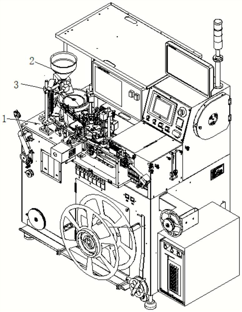
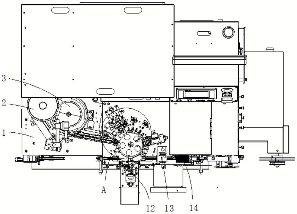
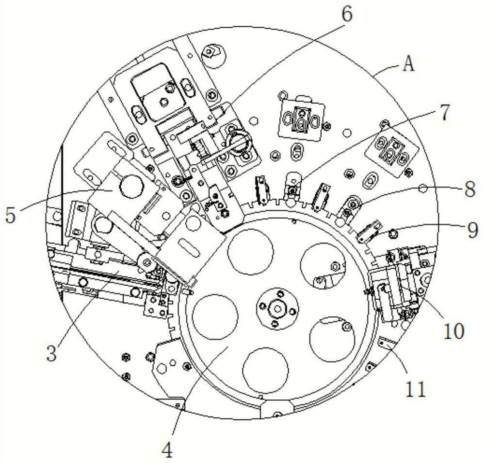
[0025] see Figure 1-6 , the present invention provides a technical solution: a fully automatic direction recognition and automatic correction mechanism, including a machine body 1, a feeding mechanism 2, a vibrating plate 3, an indexing plate 4, an automatic direction recognition component 5 and an automatic correction component 6, the upper The feeding mechanism 2 is fixedly connected to the left side of the top of the body 1, the vibrating plate 3 is fixedly connected to the left side of the top of the body 1, the discharge end of the feeding mechanism 2 is lapped on the top of the vibrating plate 3, and the indexing plate 4 is connected to the In the middle of th...


PUM


Abstract

The invention relates to the technical field of electronic component detection and packaging, in particular to a full-automatic direction recognition and automatic correction mechanism which comprisesa machine body, a feeding mechanism, a vibration disc, an index plate, an automatic direction recognition assembly and an automatic correction assembly. The feeding mechanism is fixedly connected tothe left side of the top of the machine body, the vibration disc is fixedly connected to the left side of the top of the machine body, the discharging end of the feeding mechanism is in lap joint withthe top of the vibration disc, the index plate is in transmission connection with the middle of the top of the machine body, a containing groove used for containing a filter is formed in the top of the index plate, and the discharging end of the vibration disc corresponds to the containing groove. According to the full-automatic direction recognition and automatic correction mechanism, an electronic component with wrong orientation can be identified, the automatic correction assembly can conveniently adjust and correct the orientation of the electronic component, and meanwhile, image recording can be carried out on the electronic component, so that the automation degree is high, the production cost of an enterprise can be greatly reduced, and the packaging and detection effects on the electronic component are improved.

Description

technical field [0001] The invention relates to the technical field of detection and packaging of electronic components, in particular to a fully automatic direction recognition and automatic correction mechanism. Background technique [0002] With the popularization of the application of electronic products, the application of electronic components is increasing. In order to enable automatic equipment to automatically solder components on the circuit board, it is first necessary to package the electronic components and transfer them to a continuous feeding machine. Carrier tape, and at the same time, it is necessary to check whether the electronic components are qualified. For this purpose, a packaging inspection machine is required to meet the testing and packaging operations of electronic components. However, during packaging, the vibrating plate will transport the electronic components to the indexing plate. However, it will lead to the wrong orientation of electronic co...

Claims


Application Information

Patent Timeline
Patent Type & Authority Applications(China)
IPC IPC(8): B07C5/02B07C5/344B07C5/36B65G47/244
CPCB07C5/02B07C5/344B07C5/362B65G47/244
Inventor 夏欢张勇
Owner 金动力智能科技(深圳)有限公司
Learn More