
Novel power battery pack fixing and mounting structure

A power battery pack and installation structure technology, which is applied in the direction of power devices, electric power devices, transportation and packaging, etc., to achieve the effect of low mold opening cost and convenient installation

Inactive Publication Date: 2020-11-03
苏州同捷汽车工程技术股份有限公司
View PDF0 Cites 0 Cited by
  • Summary
  • Abstract
  • Description
  • Claims
  • Application Information

AI Technical Summary

Problems solved by technology

[0003] The technical problem to be solved by the present invention is to provide a new type of installation structure for power battery packs, which is suitable for pure electric vehicles and plug-in hybrid electric vehicles. On the one hand, it solves the problem of battery pack layout space; Vehicle crash safety requirements

Method used


Image

  • Novel power battery pack fixing and mounting structure
  • Novel power battery pack fixing and mounting structure
  • Novel power battery pack fixing and mounting structure

Examples


Embodiment Construction

[0014] The present invention is described in detail below in conjunction with specific embodiment:

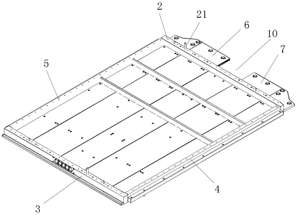
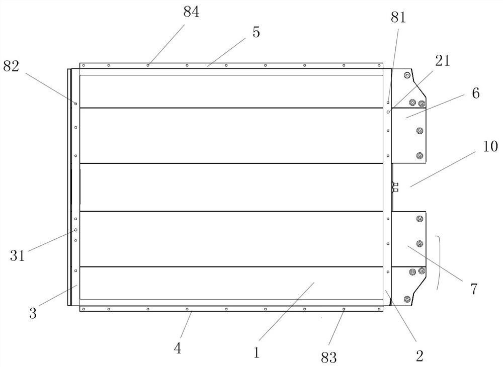
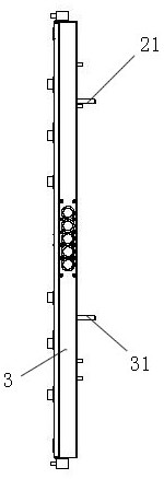
[0015] Such as Figure 1 to Figure 5 The fixed installation structure of a new type of power battery pack shown includes a floor 1, a left longitudinal beam 2, a right longitudinal beam 3, a front beam 4, a rear beam 5, a reinforcing plate upper right sealing plate 6 and a reinforcing plate right lower sealing plate 7. The floor 1 is formed by plugging and assembling five rectangular profiles, and the left side beam 2, the right side beam 3, the front beam 4, and the rear beam 5 are respectively fixed and installed on the left side of the floor 1. , right, front and rear positions, and the left side beam 2 and the right side beam 3 are respectively welded and fixed with the front beam 4 and the rear beam 5, and the left side beam 2 and the right side beam 3 , the front beam 4, and the rear beam 5 are equidistantly provided with several installation holes 81, 82, 83, 84 respect...


PUM


Abstract

The invention discloses a novel power battery pack fixing and mounting structure, and the structure comprises a floor, a left side longitudinal beam, a right side longitudinal beam, a front cross beam, a rear cross beam, a reinforcing plate right upper sealing plate and a reinforcing plate right lower sealing plate, wherein the left side longitudinal beam and the right side longitudinal beam are welded and fixed to the front cross beam and the rear cross beam correspondingly. The left longitudinal beam, the right longitudinal beam, the front cross beam and the rear cross beam are each providedwith a plurality of mounting holes at equal intervals, battery pack positioning pins are arranged on the top face of the left longitudinal beam and the top face of the right longitudinal beam respectively, and the reinforcing plate upper right sealing plate and the reinforcing plate lower right sealing plate are fixedly mounted at the upper end and the lower end of the right longitudinal beam respectively; and a wire passing gap is formed between the reinforcing plate right upper sealing plate and the reinforcing plate right lower sealing plate. The fixing structure is convenient to install on the whole vehicle, and the profile mold opening cost is low. The problem of battery pack arrangement space is solved, and the requirement of the battery for the whole vehicle collision safety is met.

Description

Technical field: [0001] The invention belongs to the technical field of automobiles, and in particular relates to a novel power battery pack fixed installation structure. Background technique: [0002] The layout of the power battery pack should not only consider the distribution of the axle load of the vehicle, but also meet the ground clearance and collision safety requirements; at present, most domestic electric vehicles are remanufactured on the basis of traditional vehicles, and the chassis and body have been greatly changed, and the development cost higher. Invention content: [0003] The technical problem to be solved by the present invention is to provide a new type of installation structure for power battery packs, which is suitable for pure electric vehicles and plug-in hybrid electric vehicles. On the one hand, it solves the problem of battery pack layout space; Vehicle crash safety requirements. [0004] In order to solve the above technical problems, the pre...

Claims


Application Information

Patent Timeline
Patent Type & Authority Applications(China)
IPC IPC(8): B60K1/04
CPCB60K1/04B60K2001/0438
Inventor 王宏春雷雨成邓建国唐为洲
Owner 苏州同捷汽车工程技术股份有限公司
Learn More