
Die forging high-strength scraper conveyor

A scraper conveyor, high-strength technology, applied in the field of conveyors, can solve the problems of shrinking space, reducing material transmission efficiency, low material transportation efficiency, etc., and achieve the effect of preventing material from spilling and reducing material transmission efficiency.

Active Publication Date: 2020-11-03
江苏旭信机械制造有限公司
View PDF10 Cites 3 Cited by
  • Summary
  • Abstract
  • Description
  • Claims
  • Application Information

AI Technical Summary

Problems solved by technology

[0002] The scraper conveyor is a device that uses the thrust of the scraper to transport materials. It has a wide range of applications in grain loading and material transportation. However, the existing scraper conveyor is prone to Due to the influence of the inclined transport channel, when there is a lot of material filling, the material is easy to slide down along the slope, causing the problem of low material transportation efficiency, and the existing scraper conveyor is in the process of material transportation, because the material is wet, the material itself With the characteristics of stickiness, the material is easy to stick to the surface of the scraper, which reduces the space for new materials around the scraper and reduces the transmission efficiency of the material. Therefore, people need die forging high-strength scraper conveyor to solve the above problems

Method used


Image

  • Die forging high-strength scraper conveyor
  • Die forging high-strength scraper conveyor
  • Die forging high-strength scraper conveyor

Examples


Embodiment

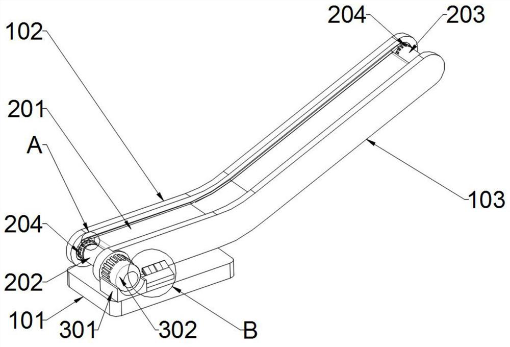
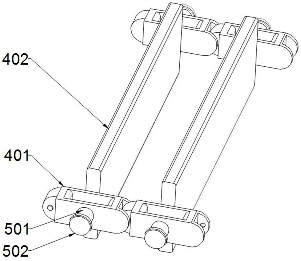
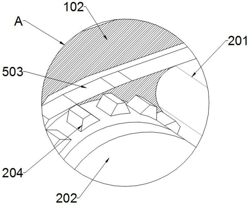
[0023] Example: such as Figure 1-7 As shown, the die-forged high-strength scraper conveyor includes a support assembly, a transmission assembly, a power source assembly, a scraping assembly, a guide assembly, a cleaning assembly, a fixed plate assembly, and a trigger assembly. The support assembly is located on the outermost side of the entire device , which plays the role of supporting other parts of the device. One end of the supporting component is provided with a transmission component, which plays the role of power transmission. One side of the transmission component is provided with a power source component. The power source component is the power source of the device. On the transmission component There is a scraping assembly, which plays the role of pushing the material to move. There is a guide assembly on the side of the scraping assembly, which plays the role of guiding and limiting the scraping assembly. One side of the guide assembly is provided with a cleaning C...


PUM


Abstract

The invention discloses a die forging high-strength scraper conveyor, and belongs to the technical field of conveyors. The die forging high-strength scraper conveyor comprises a supporting assembly, atransmission assembly and a power source assembly, wherein the supporting assembly is located on the outermost side of the whole set of die forging high-strength scraper conveyor, the transmission assembly is arranged at one end of the supporting assembly, and the power source assembly is arranged on one side of the transmission assembly. The die forging high-strength scraper conveyor is scientific and reasonable, and safe and convenient to use; and according to the die forging high-strength scraper conveyor, a curved-surface pressed rotating block is stressed to rotate by utilizing reactionthrust of materials on scrapers, the end, close to a transmission column, of the curved-surface pressed rotating block can generate upward pushing force on the transmission column, and the cambered-surface contact surfaces of cambered-surface convex blocks and filling blocks are utilized, so that the cambered-surface convex blocks push the filling blocks to support a rubber sleeve, the supported rubber sleeve can be inserted into the materials between the two adjacent scrapers, and the plurality of filling blocks act together to play a role in restraining the materials, so that the contact between the materials is more compact, and the materials are not prone to scatter in the inclined state of an inclined conveying baffle area.

Description

technical field [0001] The invention relates to the technical field of conveyors, in particular to a die-forged high-strength scraper conveyor. Background technique [0002] The scraper conveyor is a device that uses the thrust of the scraper to transport materials. It has a wide range of applications in grain loading and material transportation. However, the existing scraper conveyor is prone to Due to the influence of the inclined transport channel, when there is a lot of material filling, the material is easy to slide down along the slope, causing the problem of low material transportation efficiency, and the existing scraper conveyor is in the process of material transportation, because the material is wet, the material itself With the characteristics of stickiness, the material is easy to stick to the surface of the scraper, which reduces the space for new materials around the scraper and reduces the transmission efficiency of the material. Therefore, people need forged...

Claims


Application Information

Patent Timeline
IPC IPC(8): B65G19/06B65G19/18
CPCB65G19/06B65G19/18
Inventor 朱丹朱奕憬
Owner 江苏旭信机械制造有限公司
Learn More