A tubular crawling robot induced by a three-tube flexible actuator

A crawling robot and actuator technology, applied in the direction of pipes/pipe joints/pipe fittings, pipe components, special pipes, etc., can solve the problems of poor detection effect of flexible robots in the range of motion, and achieve small weight, good flexibility, and flexibility high effect

Active Publication Date: 2022-02-08
SHANGHAI UNIV
View PDF0 Cites 0 Cited by
  • Summary
  • Abstract
  • Description
  • Claims
  • Application Information

AI Technical Summary

Problems solved by technology

However, the robot still has an air source and air pipe that limits the robot's range of motion, which is not conducive to long-distance pipeline inspection, and the flexible robot itself has a large deformation that leads to poor detection results. Therefore, a pipeline inspection robot was invented to make it possible to realize It is particularly important to have a certain bending deformation to adapt to the curved and complex pipeline environment, and to avoid the limitation of the detection range by the robot's own hardware such as air source and air pipe.

Method used


Image

  • A tubular crawling robot induced by a three-tube flexible actuator
  • A tubular crawling robot induced by a three-tube flexible actuator
  • A tubular crawling robot induced by a three-tube flexible actuator

Examples


Embodiment 1

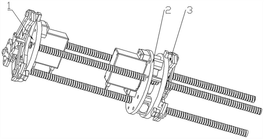
[0024] In this example, if figure 1 As shown, a tubular crawling robot induced by a three-tube flexible actuator includes a top iris mechanism adhesion device 1, a hose gear meshing drive device 2 and a bottom iris mechanism adhesion device 3; the top iris mechanism adhesion device 1 is set on On the top of the robot, the top iris mechanism adhesion device 1 located at the top of the robot is fixedly connected to one end of the three metal bellows 10 in the hose gear engagement drive device 2, and the motor fixed plate 11 in the hose gear engagement drive device 2 passes through The double-way copper column 15 is firmly connected with the bottom iris mechanism adhesion device 3 .

Embodiment 2

[0026] This embodiment is basically the same as Embodiment 1, and the special features are as follows:

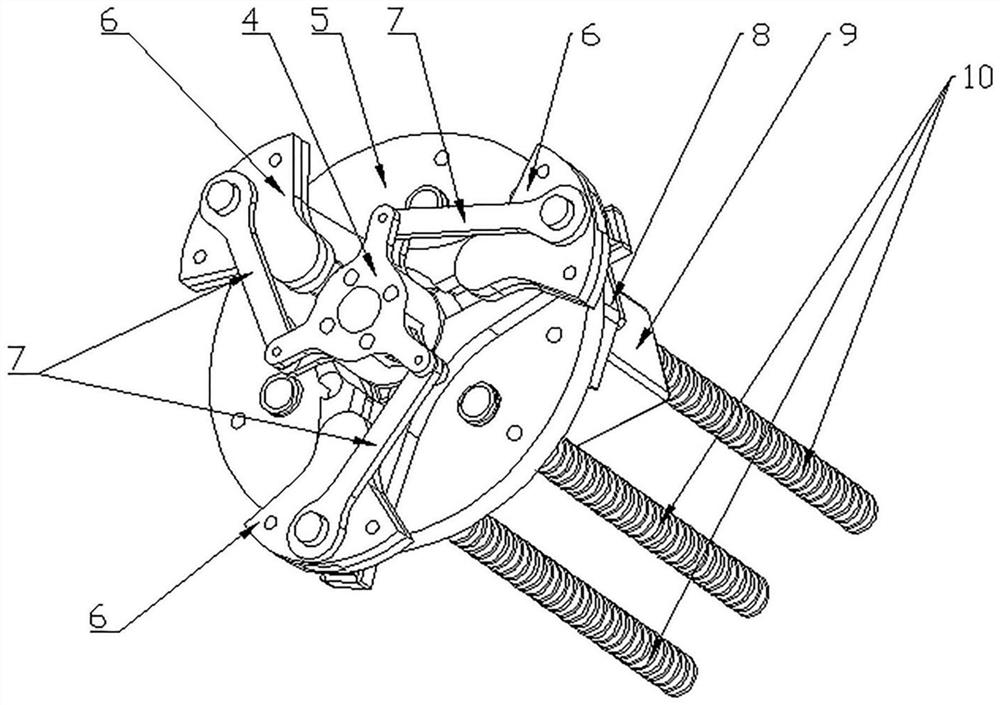
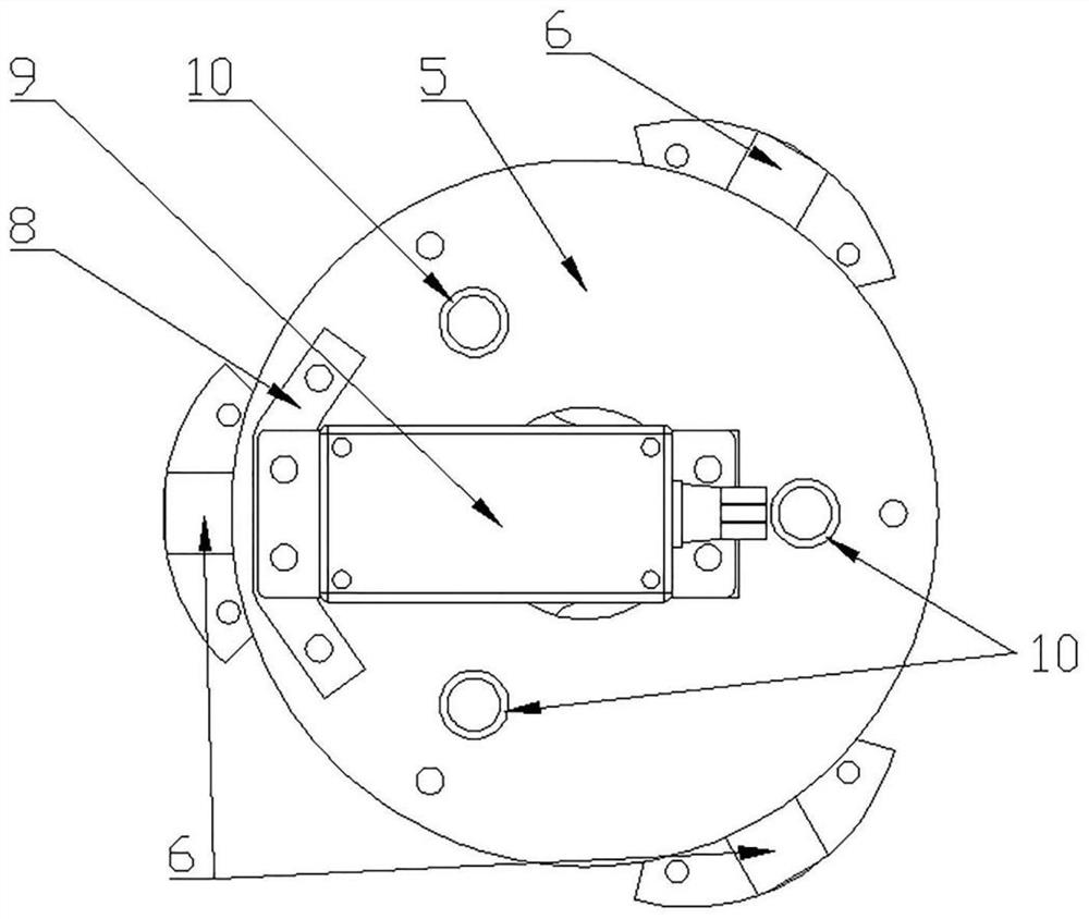
[0027] In this example, if figure 2 and image 3 As shown, the top iris mechanism adhesion device 1 includes a top crank 4, three top connecting rods 7, three top sliders 6, a top chute plate 5, a top steering gear mounting pad 8, and a top steering gear 9 The top crank 4 forms three crank slider mechanisms with three top connecting rods 7, three top sliders 6 and top chute disc 5 respectively, and the top crank 4 is fixedly connected with the top steering gear 9; the top steering gear mounting pad The block 8 is fixedly installed with the top chute plate 5 and the top steering gear 9 by bolts and nuts, and the top slider 6 and the top chute plate 5 form a contact movement pair, and the top slide block 6 can slide on the top chute plate 5. Slide in the lane. The rotation of the top steering gear 9 drives the top crank 4 to rotate, and the rotation of the top crank 4 dri...

Embodiment 3

[0029] This embodiment is basically the same as the above-mentioned embodiment, and the special features are as follows:

[0030] In this example, if Figure 4 and Figure 5 As shown, the hose gear engagement driving device 2 includes three metal bellows 10, three gears 14, three DC motors 12, three motor frames 13, a motor fixing plate 11 and three double-pass copper columns 15; three The metal bellows 10 are evenly distributed on the circumference with a diameter of 50mm at an angle of 120° to each other, and the axial ends of the three metal bellows 10 are fixedly connected with the top chute disc 5 in the top iris mechanism adhesion device 1. The threads on the outer surfaces of the three metal bellows 10 mesh with the three gears 14 respectively to form a rack and pinion mechanism. As the gears 14 rotate, the metal bellows 10 and the gears can move relative to each other. The gear 14 is fixedly connected with the DC motor 12, the DC motor 12 is fixed on one side of the mo...


PUM


Abstract

The invention discloses a tubular crawling robot induced by a three-tube flexible actuator, which comprises a top iris mechanism adhesion device, a hose gear meshing drive device and a bottom iris mechanism adhesion device, and the top iris mechanism adhesion device engages with the hose gear The three metal bellows in the driving device are fixedly connected at one end, and the fixed plate of the motor is fixedly connected with the adhesion device of the iris mechanism at the bottom through a double-pass copper column. The invention adopts a hose gear meshing driving device to drive, and the motor installed on the motor fixed plate rotates at different speeds in the same time, so that the robot can stretch and crawl in the three-dimensional space, and realize the maximum 90° bending deformation. The top and bottom iris mechanism adhesion devices are driven by the steering gear to make the robot contact or separate from the inner wall of the water pipe. The invention adopts a steering gear and a motor to drive, and gets rid of the constraint of the gas source and gas pipe on the moving distance of the pipeline robot; and the tubular crawling robot has a small structure and can be applied to the detection and maintenance of small curved pipelines.

Description

technical field [0001] The invention aims to solve the disadvantages of the traditional rigid and pneumatic flexible pipeline detection robot that cannot adapt to the narrow and curved pipeline working environment and has a small working range in the process of monitoring and maintenance of small curved pipelines, and specifically relates to a three-pipe flexible actuator induced Tubular crawling robot. Background technique [0002] In the field of robot development, how to realize the detection, maintenance and cleaning of pipeline mechanization is a major problem we face. Most pipeline robots are composed of rigid bodies, which have the disadvantages of poor flexibility and poor environmental adaptability, and cannot adapt to changing bending directions and working environments with different pipe diameters. Although the pneumatic flexible robot can realize the flexible bending of the body, most of them are large in size and need to be connected to the air pipe and air so...

Claims


Application Information

Patent Timeline
Patent Type & Authority Patents(China)
IPC IPC(8): F16L55/32F16L55/40F16L55/30
CPCF16L55/32F16L55/40F16L2101/30
Inventor 李龙蒋奕晨田应仲马培峰金滔
Owner SHANGHAI UNIV
Why Eureka
Try Eureka