
A clamping device for DR equipment suitable for complex environments on site

A complex environment, clamping device technology, applied in mechanical equipment, material analysis using radiation, machine/support, etc., can solve the problems of difficult installation and fixation, complex structure, etc., to improve detection efficiency, shorten detection time, save money The effect of detection time

Active Publication Date: 2022-06-17
ELECTRIC POWER SCI & RES INST OF STATE GRID TIANJIN ELECTRIC POWER CO +2
View PDF0 Cites 0 Cited by
  • Summary
  • Abstract
  • Description
  • Claims
  • Application Information

AI Technical Summary

Problems solved by technology

[0004] The structure of the above-mentioned patent and the present application is complicated, and it is not easy to install and fix

Method used


Image

  • A clamping device for DR equipment suitable for complex environments on site
  • A clamping device for DR equipment suitable for complex environments on site
  • A clamping device for DR equipment suitable for complex environments on site

Examples


Embodiment Construction

[0027] The present invention will be further described in detail below through specific examples. The following examples are only descriptive, not restrictive, and cannot limit the protection scope of the present invention.

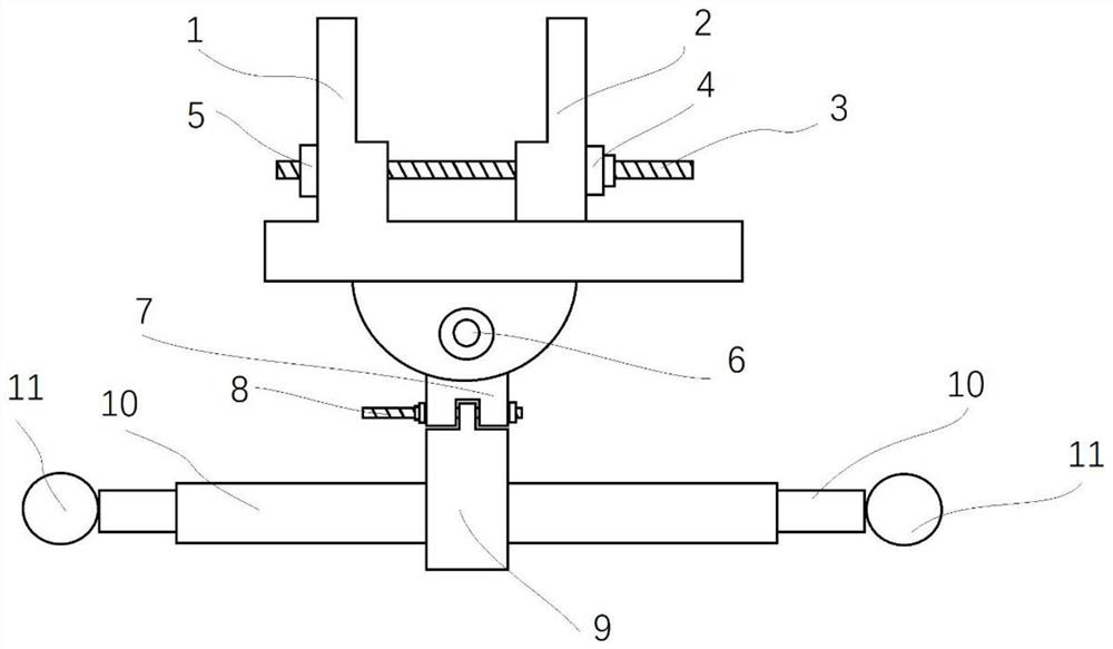
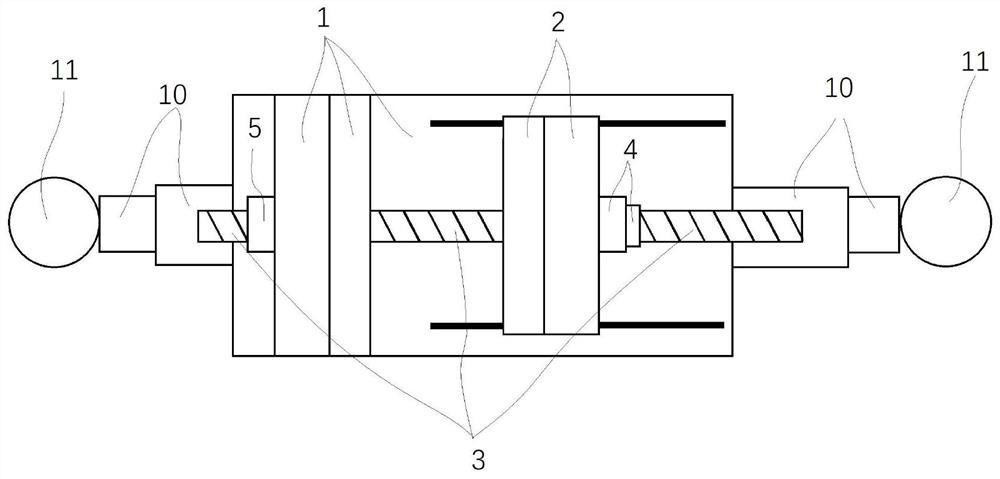
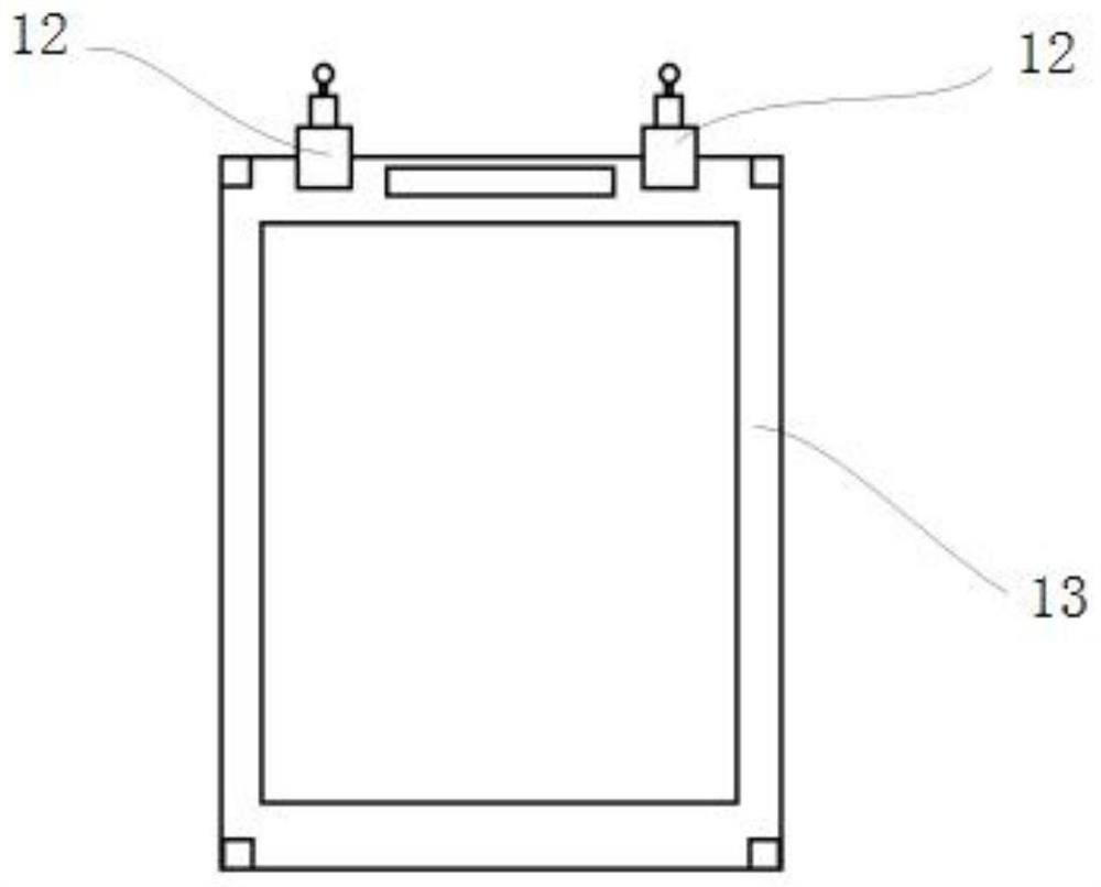
[0028] A DR equipment clamping device suitable for complex on-site environment includes a receiving screen fixture, a DR ray machine fixture and a universal bracket, and the DR ray machine fixture is installed on two universal brackets arranged symmetrically at intervals.

[0029] The receiving screen fixture 12 includes a fixture platform (1), a connecting head (7), a telescopic rod insertion head (9), a telescopic rod (10), and a telescopic rod insertion head ( 9), put the telescopic rod (10) on the telescopic rod insertion head (9). The clamp platform (1) provides a clamping function, which can clamp the receiving screen.

[0030] The fixture platform (1) is composed of a fixed end chuck, a platform, and a hemispherical device with bolt holes. A fixe...


PUM


Abstract

The invention relates to a clamping device for DR equipment suitable for complex environments on site, including a receiving screen clamp, a DR-ray machine clamp and a universal bracket, and the DR-ray machine clamp is installed on two universal brackets arranged symmetrically at intervals. The DR ray machine fixture includes a support plate, a movable clamp rod, a chuck, and a universal bracket connector. Two long holes are made in parallel on the support plate, and two movable clamps are installed between the two long holes. The two movable clamping rods and the two long holes are fixed by locking bolts, four chucks are symmetrically fixed on the opposite sides of the two movable clamping rods, and two ten thousand chucks are symmetrically fixed on both sides of the bottom surface of the support plate. to the bracket connector. The invention can quickly, stably and accurately fix the DR equipment and the receiving screen in the complex field environment, improve the detection efficiency and shorten the detection time.

Description

technical field [0001] The invention belongs to the technical field of electric equipment detection, and relates to DR detection, in particular to a DR equipment clamping device suitable for on-site complex environments. Background technique [0002] As a new type of X-ray detection technology, the DR detection method is widely used in the X-ray detection of GIS equipment in substations. However, due to the small interval between GIS equipment in the substation and the complex on-site environment, the receiving screen of the DR equipment is not easy to fix, and the angle of the DR equipment is not easy to swing. It is difficult to use on-site. There are often problems such as deviation between the placement position of the receiving screen and the expected position, the receiving screen is easy to fall, and the DR equipment cannot be placed, which affects the test results and increases the test time. [0003] CN210330593U discloses a foldable and convenient DR rack, comprisi...

Claims


Application Information

Patent Timeline
Patent Type & Authority Patents(China)
IPC IPC(8): F16M11/04F16M11/12F16M11/14F16M11/18F16M11/28F16M11/42G01N23/04
CPCF16M11/041F16M11/048F16M11/121F16M11/14F16M11/18F16M11/28F16M11/42G01N23/04
Inventor 李田叶芳齐文艳傅思伟张迅达管森森于金山李庆钊温力文黎陈韶瑜
Owner ELECTRIC POWER SCI & RES INST OF STATE GRID TIANJIN ELECTRIC POWER CO
Learn More